


AG033586EE
ZP-AG03E
IDAX 300/322/350
31
4 IDAX 5 SOFTWARE
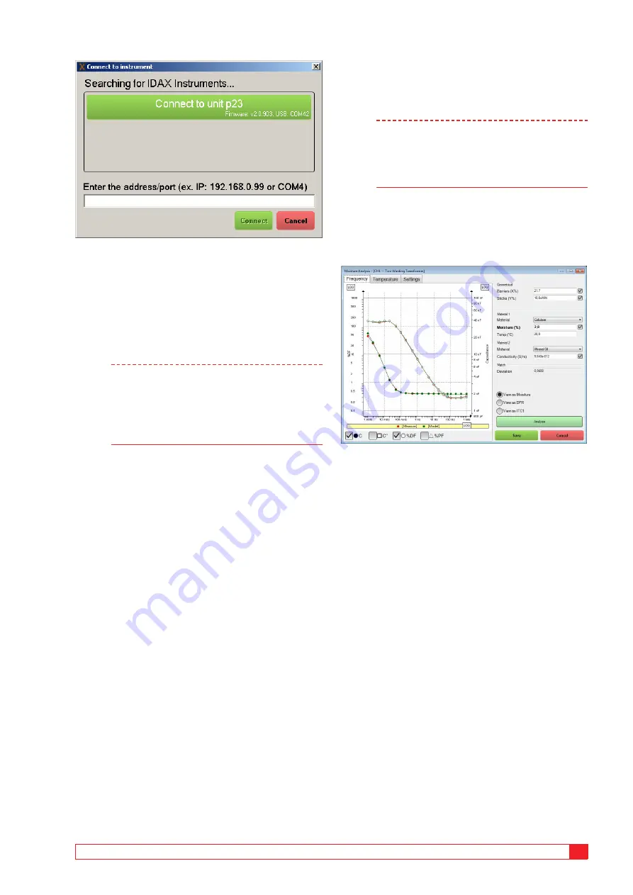
2]
Press button “Connect to unit p23” to
connect to IDAX unit identified by “p23”.
In case this automatic detection does not
work you may alternatively enter the
address/port in the field at the bottom of the
window and then press the Connect button.
Any IDAX connected via USB will be shown in
green colour and via Ethernet in blue colour.
Note
Connection via Ethernet can be done by
direct cable or via Network/LAN-hub; using
a LAN you will be able to operate the IDAX
from remote places. In case you have several
instrument connected via Network/LAN-hub,
make sure connect to correct instrument.
3]
When the IDAX system is connected, the
button will change label to a Disconnect
button and you may use this button to
disconnect the IDAX.
When a long and time consuming test is initiated, it
is possible to disconnect the PC from the IDAX and
let the unit store the measurement data until it is
connected again. In cases where this is possible, the
button is labelled Run Standalone.
Settings section
In this section you may change the settings for the specific
test:
▪
Change colour of e.g. graphs by pressing the color
button.
▪
Change Test mode by clicking the test mode button
(currently set to measure CHL for this test
▪
Change test voltage level by changing test voltage.
▪
Change temperature of object/insulation tested.
Start/Stop/Remake
1]
Press button“Start”to start a test, and press
the button “Stop” to stop a test.
If you have marked an executed test in the
legend, you are not able to override this test
and therefore the button change function
and is labelled “Remake”. The Remake
guides you to make a new test as a copy of
the executed test.
Note
Using the Remake-button will make the
settings used in the previous measurement
but not copy the settings from the section
“Settings tab” such as frequency, generator
and cable setting.
Analysis window
This tab performs insulation modelling of the
measured Dielectric Frequency Response, DFR.
1]
Press “Analyze” to make the modelling
software to perform an automatic
“matching” of a modelled insulation (X-Y
model) with the measured response.
2]
It is possible to select “View as ITC1” but
it should be done only in cases when it is
justified, namely if insulation is consisting of
a single material and it is listed under Single
Materials in Settings.
Geometrical
Barriers (%X) represent the amount of barriers
in relation to total insulation thickness and sticks
(%Y) represent the area the sticks cover. If checked
(default and recommended), the analysis function
automatically calculates a geometry of the modelled
insulation.
Limits for X/Y depend on the test object and default
settings as in table below. Recommended X&Y
Parameters for insulation modelling.
Содержание IDAX 300
Страница 2: ......
Страница 5: ...AG033586EE ZP AG03E IDAX 300 322 350 5...
Страница 11: ...AG033586EE ZP AG03E IDAX 300 322 350 11 2 Safety...
Страница 19: ...AG033586EE ZP AG03E IDAX 300 322 350 19 3 Instrument description...
Страница 33: ...AG033586EE ZP AG03E IDAX 300 322 350 33 4 IDAX 5 Software...
Страница 35: ...AG033586EE ZP AG03E IDAX 300 322 350 35 5 Calibration...
Страница 43: ...AG033586EE ZP AG03E IDAX 300 322 350 43...
Страница 45: ...AG033586EE ZP AG03E IDAX 300 322 350 45 8 Specifications...


