background image

Side burner

lgniter wire

Side burner

3mm

23

Assembly Instructions

Fig. 29

9.

Pulse Igniter Module and Battery Assembly

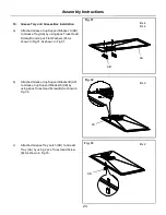
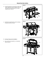
a)    Remove igniter battery cap and lock washer 

from igniter.Insert Pulse Igniter Module 
(Z)throuth from back of side burner control 
panel,secure lock washer from front of side 
burner control panel.Then insert the ignition 
wires to the Pulse Ignition Module (Z) located on 
the right side burner control panel.As shown in 
Fig. 28. 

b) Install Battery(AJ) into ignition box with positive 

terminal (+) facing outward.

c)

Repleace the ignition battery cap after the 
Battery has been installed.As shown in Fig.29.

d)    Adjust the side burner igniter wire and side 

burner.As shown in Fig.30.

Fig. 30

Fig. 28

AJ

Z

Содержание Blaze 600 Black

Страница 1: ...ed to be installed in or on recreational vehicles and or boats WARNING To reduce the risk of fire burn hazard or other injury read the manual carefully and completely before using your grill Blaze 600 Black USER MANUAL ASSEMBLY INSTRUCTIONS Important Read these instructions and warnings carefully so as to familiarize yourself with the appliance before connecting it to its gas container Keep these ...

Страница 2: ...t Leak Testing 2 7 8 9 10 11 12 13 14 26 27 28 28 29 DANGER If you smell gas 1 Shut off gas to the appliance 2 Extinguish any open flame 3 Open lid 4 If odour continues keep away from the appliance and immediately call your gas supplier or your fire department WARNING 1 Do not store or use petrol or other flammable liquids or vapour in the vicinity of this or any other appliance 2 Do not store spa...

Страница 3: ...o not fill cooking vessel beyond maximum fill line 5 Heated liquids remain at scalding temperatures long after the cooking process Never touch cooking appliance while it is still hot 6 This appliance is not intended for and should never be used as a heater 7 If a fire should occur keep away from the appliance and immediately call your fire department Do not attempt to extinguish an oil or grease f...

Страница 4: ...o obstructions and the burn back still occurs call a technician to examine the appliance and make any necessary repairs Do not make any adjustments or modifications to this braai a qualified LP gas technician should do any adjustments To reduce the chance of BURN BACK you must clean the burner tubes before assembling your braai and at least once a month for maintenance Also perform this burner tub...

Страница 5: ...rs is permissible only if the cylinder is disconnected and removed from the outdoor cooking gas appliance When your gas braai is not in use the gas must be turned off at LP gas cylinder The gas must be turned off at the supply cylinder when the outdoor cooking gas appliance is not in use LP gas cylinder must be stored outdoors in a well ventilated area and out of reach of children and pets Disconn...

Страница 6: ...e DO NOT USE ALUMINUM FOIL TO LINE THE BRAAI RACKS OR BRAAI BOTTOM This can severely upset combustion air flow or trap excessive heat in the control area DO NOT LEAVE THE BRAAI UNATTENDED WHILE COOKING SAFETY PRACTICES TO AVOID PERSONAL INJURY When properly cared for your braai will provide safe reliable service for many years However extreme care must be used as the braai produces intense heat th...

Страница 7: ...e control area For proper lighting and performance of the burners keep the burner ports clean It is necessary to clean them periodically for optimum performance The burners will only operate in one position and must be mounted correctly for safe operation Clean the braai with caution To avoid steam burns do not use a wet sponge or cloth to clean the braai while it is hot Some cleaners produce toxi...

Страница 8: ...nt right 1pc 1pc E Swivel caster 2pcs F Swivel caster with brake 2pcs G Side panel 3pcs H Side panel right top 1pc I Bottom panel 1pc J Cylinder support bracket 2pcs K Door iron piece 1pc L Triangle bracket right 1pc M Triangle brackets left 1pc N Cart frame 1pc O Door left 1pc P Door right 1pc Q Door handle D Cart leg rear right 2pcs ...

Страница 9: ...side shelf 2pcs X Side tube burner 1pc Y Control knob 1pc Z Pulse igniter module 1pc AA Grease tray 1pc AF Flame tamer 6pcs AG Cooking grid 2pcs AE Grease box 1pc AH Warming rack 1pc AI Side burner cooking grid 1pc AJ 1 5 Volt A Size Alkaline Battery 1pc AB Grease try support bracket A 2pcs AC Grease try support bracket B 1pc AD Grease try latch 1pc ...

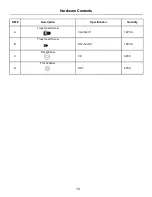
Страница 10: ...REF Description Specification Quantity A Truss Head Screw 1 4 20x3 5 14PCS B Truss Head Screw 5 32 32x2 5 18PCS C Flat Washer 1 4 6PCS D Flat Washer 5 32 4PCS 10 Hardware Contents ...

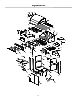
Страница 11: ... 10 8 9 11 11 12 13 14 20 19 18 17 15 16 21 22 23 24 25 26 27 28 29 30 34 33 32 31 35 36 37 39 40 42 33 41 43 44 45 46 30 35 47 48 49 49 50 49 51 52 53 54 55 58 59 57 56 61 60 62 63 64 65 66 67 68 69 38 11 Exploded view ...

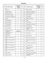
Страница 12: ...d buffer B 1 2 33 Side shelf support bracket 1 2 12 Main burner bowl assembly Non replaceable 1 34 Side shelf end cap left 1 1 13 Main burner pin assembly 1 6 35 Utensil hook 1 6 14 Main burner 1 6 36 Side burner lid 1 1 15 Main burner igniter wire A 1 1 37 Side burner lid hinge rod 1 2 16 Main burner igniter wire B 1 1 38 Side burner lid hinge rod pin 1 2 17 Main burner igniter wire C 1 2 39 Side...

Страница 13: ...ke 1 2 48 Triangle bracket left 1 1 61 Swivel caster 1 2 49 Side panel 1 3 62 Door right 1 1 50 Side panel right top 1 1 63 Door left 1 1 51 Bottom panel 1 1 64 Door handle 1 2 52 Cylinder support bracket 1 2 65 Grease box 1 1 53 Door iron piece 1 1 66 Grease cup support bracket A 1 2 54 Cart frame 1 1 67 Grease cup support bracket B 1 1 55 Door magnet 1 2 68 Grease try 1 1 56 Cart leg rear left 1...

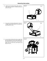
Страница 14: ...assembled on the Cart Leg Rear Left B and Cart Leg Front Left A Attach Cart Leg Rear Left B and Cart Leg Front Left A to Side panel G by aligning the holes on the Side Panel G Tighten the screws that were loosened above As shown in Fig 1 Fig 3 14 Assembly Instructions Fig 1 Fig 2 A B A B D C b Loosen but do not remove the screws that are pre assembled on the Cart Leg Rear Left B and Cart Leg Front...

Страница 15: ...ig 4 2 Bottom Panel Assembly a Loosen but do not remove the screws that were pre assembled on the side of the Bottom Panel I align the holes on the Cart Leg Front Left A and Cart Leg Rear Left B Cart Leg Front Right C and Cart Leg Rear Right D then place the cart legs onto the screws that were loosened in the Bottom Panel I As shown in Fig 5 b Attach Swivel caster with brake F to Cart Leg Rear Lef...

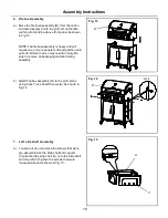
Страница 16: ...mbled on Cart Leg Rear Left B and Cart Leg Rear Right D and four screws pre assemble on bottom panel I Align the holes of the triangle brackets Right L triangle brackets Left M with the screws in the Cart Leg Rear Left B and Cart Leg Rear Right D Then tighten the screws As shown in Fig 8 Note The flat portion of the triangle should face the rear of the grill 4 Cylinder Support Bracket Assembly Mou...

Страница 17: ... that were loosened above As As shown in Fig 10 b Unscrew the screws that were pre assembled on the Door handle Q Attach Door handle Q onto the Door Left O and Door Right P Tighten the screws that were unscrew above As shown in Fig 11 c Put the door hinge in the hole in the bottom panel then press the two doors hinge top and slide into the hole in the cart Frame As shown in Fig 12 O P Q K ...

Страница 18: ...e to do so may result in injury Be sure to remove all packaging material during assembly b Attach Firebox assembly R to the grill cart by using 4 pcs Truss Head Screws A As shown in Fig 14 7 Left side shelf Assembly a Loosen but do not remove the screws that were pre assembled on the Side shelf end cap left V attached the side shelf U onto the Side shelf end cap left V Tighten the screws that were...

Страница 19: ... 2 pcs Truss Head Screw B to connect Triangle braket for side shelf V and side shelf U As shown in Fig 17 d Loosen but do not remove the 2 pcs screws that were pre assembled on the firebox assembly R left side attached left side shelf onto the firebox Tighten the screws that were loosened above As shown in Fig 18 Fig 17 Fig 18 Bx 2 Bx 2 V V U U ...

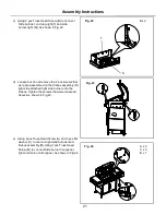
Страница 20: ...anel As shown in Fig 19 8 Right Side Burner Assembly a Loosen but do not remove the screw which is pre assembled on the outside firebox Side burner end cap right T attached the side burner end cap right T onto the Side burner right S Tighten the screws that were loosened above As shown in Fig 20 b Using 2 pcs Truss Head Screw B to connect Side burnder end cap right T and side burner right S As sho...

Страница 21: ...re assembled on the firebox assembly R right side attached right side burner onto the firebox Tighten the screws that were loosened above As shown in Fig 23 e Using 3pcs Truss Head Screw A and 3 pcs flat washer C to connect right side burnder and firebox assembly R Using 1pcs Truss Head Screw B to connect Side burner front panel right and main control panel As shown in Fig 24 Fig 24 Bx 2 A x 3 C x...

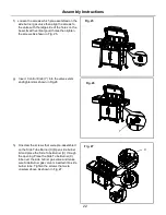
Страница 22: ...As shown in Fig 25 g Insert Control Knob Y into the valve setem and tightenit As shown in Fig 26 h Unscrew the screws that were pre assembled on the Side Tube Burner X Open side burner lid and place the Side Tube Burner X through the opening Place the Side Tube Burner X tube over the side burner gas valve and make sure Side Burner gas valve is inserted into side burner tube Tighten the screws that...

Страница 23: ...el secure lock washer from front of side burner control panel Then insert the ignition wires to the Pulse Ignition Module Z located on the right side burner control panel As shown in Fig 28 b Install Battery AJ into ignition box with positive terminal facing outward c Repleace the ignition battery cap after the Battery has been installed As shown in Fig 29 d Adjust the side burner igniter wire and...

Страница 24: ...cs Truss Head Screw B and 2 pcs Flat Washers D As shown in Fig 31 As shown in Fig 31 b Attached Grease Cup Support Bracket B AC to Grease Cup Support Breaket A AB by using 2pcs Truss Head Screw B As shown in Fig 32 c Attached Grease Tray Latch AD to Greast Tray AA by using 2 pcs Truss Head Screw B As shown in Fig 33 Fig 33 Bx 4 Dx 4 Bx 2 Bx 2 AA AB AC AD ...

Страница 25: ... sliding the tray on the glides at the rear of the grill until centered under the cooking area As shown in Fig 34 e Install the Grease Box AE under the Grease Tray AA As shown in Fig 35 11 Cooking Components Installation a Place the Flame Tamers AF in to the grill As shown in Fig 36 Fig 36 AA AE AF ...

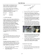
Страница 26: ...ing Grid AI into the side burner As shown in Fig 38 1 Connecting Regulator To The LP Tank 1 LP tank must be properly secured onto grill Refer to assembly section 2 Turn all control knobs to the OFF position 3 Turn LP tank OFF by turning the regulator handle clockwise to a full stop 4 Remove the protective cap from LP tank valve Always use cap and strap supplied with valve As shown in Fig 39 Fig 39...

Страница 27: ... hose regulator assembly for connection to a standard 9kg LP gas cylinder 52cm high 30cm diameter To connect the LP gas supply cylinder please follow the steps below 1 Make sure cylinder valve is in the complete off position turn clockwise to stop 2 Check cylinder valve to ensure it has proper internal female threads 3 Make sure all burner valves are in their off position 4 Inspect valve connectio...

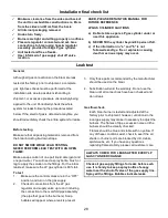
Страница 28: ...ORM LEAK TEST WITH AN OPEN FLAME Make a soap solution of one part liquid detergent and one part water You will need a spray bottle brush or rag to apply the solution to the fittings For the initial leak test make sure the LP gas cylinder is 80 full To test 1 Make sure the control valves are in the OFF position and turn on the gas supply 2 Check all connections from the LP gas regulator and supply ...

Страница 29: ... valve Other types of caps or plugs may result in leaking of LP gas The gas must be turned off at the supply cylinder when the unit is not in use If the appliance is stored indoors the cylinder must be disconnected and removed from the appliance Cylinders must be stored outdoors in a well ventilated area out of the reach of children Your gas braai is ready to use 29 Leak Test ...

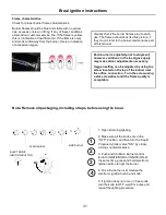
Страница 30: ...raai is preheated the faster the meat browns and the darker the braai marks DO NOT LEAVE THE BRAAI UNATTENDED WHILE COOKING WARNING IMPORTANT Before igniting Inspect the gas supply hose prior to turning the gas ON If there is evidence of cuts wear or abrasion it must be replaced prior to use Do not use the braai if the odour of gas is present Do not use any other hose connection other than the reg...

Страница 31: ...f any of these conditions exist call our customer service line If the flame is yellow this is a indication of insufficient air If the flame is noisy and tends to lift away from the burner this is a indication of excessive oxygen Each burner is adjusted prior to shipment however variations in the local gas supply may make minor adjustments necessary Oxygen setting can be adjusted by using the screw...

Страница 32: ...eak off and clog the port If insects or other obstructions are blocking the flow of gas through the burner you will need to call our customer care Grease tray cleaning The grease tray should be emptied and wiped down periodically and washed with a mild detergent and warm water solution A small amount of sand may be placed in the bottom of the grease tray to absorb the grease Check the grease tray ...

Страница 33: ...ods depending on the type of food and the cooking temperature The braai lid should be closed during the preheating time period Food that requires a high cooking temperature needs a preheating period of five minutes food that requires a lower cooking temperature needs only a period of two to three minutes Cooking temperatures High Use this setting for quick preheating for searing steaks and chops a...

Страница 34: ...or Braai only heats to 200 300 degrees Check to see if the fuel hose is bent or kinked Make sure the braai area is clear of dust Make sure the burner and orifices are clean Check for spiders and insects The regulator has a safety device that restricts the flow of gas in the event of a leak This safety device can be triggered without a gas leak To reset the safety device turn off all burners and cl...

Страница 35: ...cylinder any resulting damage to the product will void the warranty This product is intended for use with the supplied low pressure 2 8kPa LP gas regulator use with any other type of pressure regulator and any resulting damage to the product will void the warranty It is the responsibility of the product owner to safely store and protect the braai from the elements covers can be purchased separatel...

Страница 36: ...ilure to follow all instructions in this Use Care Guide may lead to fire or explosion which could result in property damage personal injury or death This appliance complies with the requirements of SANS 1539 36 www megamaster co za Manufactured in China Distributed by Mega Group PO Box 15 Woodlands 0027 South Africa Tel 27 0 12 802 1515 Blaze 600 Black ...

Отзывы: