background image

M

AINTENANCE

38

Check solar heat transfer fluid
The heat transfer fluid must be checked every year with regard to its antifreeze and pH value. (7.0 - 9.5) – Check antifreeze 
using antifreeze tester. Target value is approximately -21 deg C (40% concentration). Replace fluid if necessary.

Maintenance of the collector
The collector or the collector array must be checked/serviced annually to check for any damage, leaks or contamination.
In areas where there may be a build up of dirt on the collector, only non-abrasive cleaning materials and methods should be 
used to clean the collectors and mounting system components.

Benchmark™ 
On completion of any maintenance or service of the Megaflo Eco SolaReady, the Benchmark™ “Installation, Commissioning 
and Service Record” should be filled in to record the actions taken and the date the work was undertaken (page 50).

Fault finding
The Fault finding flow diagrams (Fig 32) will enable operational faults to be identified and their possible causes rectified. 
Any work carried out on the Megaflo Eco SolaReady unvented water heater and its associated controls MUST be carried out 
by a competent installer for unvented water heating systems. In case of doubt contact the Megaflo Eco SolaReady Service 
Department.

Fault finding

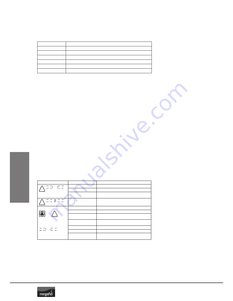
Solar differential temperature controller error messages
1. Some system failure modes can be recognised by the solar differential temperature controller and will be indicated by an 
error message on the controller display. Refer to the table below for details of possible errors and suggested measures to 
rectify.
NOTE: These error messages wil automatically reset when the fault has been rectified. In the case of the circulation error this 
may take a few minutes to clear once normal flow has resumed.

42

© Baxi Heating UK 2012

14.0

Fault finding

14.1

Failures with error message

1. Some system failure modes can be recognised by the solar
differential temperature controller and will be indicated by an
error message on the controller display. Refer to the table
below for details of possible errors and suggested measures to
rectify.

NOTE:

These error messages wil automatically reset when

the fault has been rectified. In the case of the circulation error
this may take a few minutes to clear once normal flow has
resumed.

Error representation on display Possible reasons

Measures

• Sensor wire broken

• Check wire

• Sensor defect

• Check sensor resistance, if necessary exchange sensor

• Sensor missing

• Check parameter settings and sensor installation

requirements

• Short circuit in sensor wire

• Check wire

• Sensor defect

• Check sensor resistance, if necessary exchange sensor

• Error in pump connection

• Check cabling

• Pump defect

• Exchange pump

• Air in the system

• Check the float of the flow meter moves

when the system runs (if visible)

• Connection with flow 

• Check wire

meter defect

• Sensor wire broken

• Check wire

• Sensor defect

• Check sensor resistance, if necessary exchange sensor

• Sensor missing

• Check parameter settings and sensor installation

requirements

!

!

!

+

Circulation error:  no flow

Additionally at energy
productivity measurement:

flashing

flashing

flashing

% volume

Density at 20ºC g/cu.cm

Refractive Index nD20

Frost protection ºC

25

1.023

1.3627

-10

30

1.029

1.3690

-14

35

1.033

1.3747

-17

40

1.037

1.3801

-21

45

1.042

1.3855

-26

50

1.045

1.3910

-32

Содержание Eco SolaReady

Страница 1: ...Hot Water Cylinders MEGAFLO Eco SolaReady Unvented MEGAFLO Eco SolaReady Product Guide...

Страница 2: ...15 Direct model 17 Indirect model 18 Installation of solar differential temperature controller 21 Commissioning Commissioning 22 Commissioning of solar primary system 23 Commissioning of hydraulic st...

Страница 3: ...nels its temperature is raised The heated fluid is circulated through a heat exchanger coil in the base of the Megaflo Eco SolaReady solar storage cylinder transferring the heat gained to the stored w...

Страница 4: ...cotland or Building Regulation P5 Northern Ireland and the Water Fitting Regulations England and Wales or Water Byelaws Scotland Following Installation and Commissioning the operation of the heater sh...

Страница 5: ...team heating plant unless additional and appropriate safety devices are installed Ascending spray type bidets or any other Class 5 back syphonage risk requiring that a Type AA AB AD or AG air gap be e...

Страница 6: ...s product is made from many recyclable materials therefore at the end of its useful life it should be disposed of at a Local Authority Recycling Centre in order to realise the full environmental benef...

Страница 7: ...5 175 0 79 22 5 19 24 5 Table 2 Size Unit weight kg Auxiliary volume litres Heat up times mins Empty Full Lower 3kW Upper and lower 6kW Upper 3kW 260 47 3 307 3 170 178 89 60 780 770 C B A F D DIMENS...

Страница 8: ...is no requirement to site it close to the unit it can be located at a point where the mains supply enters the premises if this is more convenient but you must install a non return valve just after the...

Страница 9: ...e plumbed to the inlet connection of the Megaflo Eco SolaReady unit No other valve should be fitted between the Pressure Relief Expansion Valve and the cylinder inlet Outlet to Megaflo eco Solar Mains...

Страница 10: ...atmosphere see page 14 Discharge Pipework Isolating Regulating Valves as required Temperature Pressure Relief Valve HWS supply Balanced HWS and MCWS to bathrooms showers cloakrooms etc DOC DOC DOC DO...

Страница 11: ...l mounting bracket is supplied for this purpose NOTE DO NOT USE THE POTABLE WATER EXPANSION VESSEL SUPPLIED WITH THE MEGAFLO ECO SOLAREADY FOR ANY OTHER PURPOSE IT MUST NOT BE USED IN PLACE OF THE SOL...

Страница 12: ...ust be left open to atmosphere The discharge pipe should not be blocked or used for any other purpose The discharge connections from the Pressure Relief Expansion Valve and the Temperature Pressure Re...

Страница 13: ...ter for prolonged periods should be used Worked example of discharge pipe sizing This example is for a G temperature relief valve with a discharge pipe D2 having 4 No elbows and length of 7m from the...

Страница 14: ...l outlet size of the safety device between 18 and 27m at least 3 sizes larger and so on bends must be taken into account in calculating the flow resistance See Diagram 1 Table 1 and the worked example...

Страница 15: ...ework collector and the level of the hydraulic pump station determines the static head for the system The static head is 0 1 bar times this height in metres This static head is used when setting the s...

Страница 16: ...to the hydraulic station Fig 16 Item 2 so that the vessel can be connected to the vessel connection of the safety group Fig 16 Item 3 using the flexible pipe Fig 16 Item 4 supplied Note Solar expansio...

Страница 17: ...n the event of a thermostat failure The thermal cut out reset button position is indicated on Figure 13 DO NOT BYPASS THE THERMAL CUT OUT IN ANY CIRCUMSTANCES The lower immersion heater can be operate...

Страница 18: ...ut operate Figure 16 diagrams A B D and E detail the wiring required between these controls and the motorised valve Wiring to external controls is made via the terminal block fitted The cable should b...

Страница 19: ...4 5 6 7 8 9 10 11 12 13 14 15 16 Link 7 8 N 8 3 5 1 2 3 GY BL BR GR OR Cylinder auxiliary controls DHW 2 port valve N 6 2 5 4 N GY BL BR GR OR L N CH 2 port valve CH pump Solar o temp cutout Solar pum...

Страница 20: ...N A1 N A2 N A3 N T1 T2 T4 T5 T7 11 12 Solar differential controller Solar pump Solar controller 1 L 1 2 Solar o temp cutout Diagram E In conjunction with auxiliary heating boiler with a 3 port mid pos...

Страница 21: ...cables must be secured suitable strain relief bushes or devi 6 The controller must be earthed 9 4 230 240V connection 1 For 230V connections you must 2 The mains supply to the controll double pole is...

Страница 22: ...t Units Switch on the electrical supply to the immersion heater s and allow the unit to heat up Check that the thermostat operates correctly A storage temperature of approx 60 C is recommended If nece...

Страница 23: ...lating valve with integral thermometer in the flow Fig 19 Item 4 in the direction indicated by the arrow to a 45 position to open the non return valve Ensure that the right hand isolating valve with i...

Страница 24: ...ve Fig 19 Item 5 back 90 clockwise until the dot on the bezel is back at 12 o clock Turn the slot of the adjusting screw Fig 19 Item 3 back to the horizontal position Commissioning of hydraulic statio...

Страница 25: ...follows Item 2 Scroll upwards moves up through the available functions of the sub menu Item 3 Scroll left return to main menu Item 4 Scroll down moves down through the available functions of the sub m...

Страница 26: ...Indication of minimum temperature storage tank s Resettable to current temperature Yes max 65 C 26 Baxi Heating UK 2012 11 0 Commissioning 11 3 Menu Info In this menu mode all measured v are shown If...

Страница 27: ...7K 3K 15 65 C Indication dT min 3 K dT max 7 K max 65 C 65 C MAX Storage tank switch on differential dTon 100 40 C 2 min 00 00 1 2 3 Ti dT min 3K Tim co max 23 59 1 2 3 Ti max 20 00 4 Tim Sto min 06 0...

Страница 28: ...ed WARNING During manual operation the regulation of the system Temperature con System temperature could be extremely h 2 To avoid inadmissible operating states this changes into Indication after appr...

Страница 29: ...on 0 off 1 on 0 3 40 C Recooling storage tank temperature 30 90 C 40 C 4 0 Tube collector function time controlled 0 off 1 on 0 5 2 Energy yield measurement off 0 2 Note This solar collector has the a...

Страница 30: ...n i n o i t a c i d n I n o i t p i r c s e D l o b m y s c i h p a r G Measuring points assignment Temperature measuring point collector array 1 Temperature measuring point collector array 2 Tempera...

Страница 31: ...rage temperature 65 C Pump operation starts when the collector temperature exceeds the cylinder temperature by more than dTon and continues while the collector temperature is above cylinder temperatur...

Страница 32: ...dT 10k TTh 40 C on A3 off 11 0 Commissioning of solar controller 11 13 Rotational speed regulation 1 The solar circulation pump on 230V outputs A1 and A2 can be operated either in switch mode two poin...

Страница 33: ...is activated until the adjusted frost protection start temperature 5K is reached The minimum runtime of the pump is 5 minutes For safety reasons the function is deactivated if the temperature of the p...

Страница 34: ...against the rear thermal insulation section Fig 31 Item 3 until it clips into place Benchmark Log Book On completion of the installation and commissioning procedures detailed in this Product Guide th...

Страница 35: ...ent C 5 6 1 k n a t e g a r o t S Maximum storage temperature K 7 1 k n a t e g a r o t S switch on difference dTon K 3 1 k n a t e g a r o t S switch off difference dToff Minimum pump power on 100 ro...

Страница 36: ...ar bar bar bar bar bar bar bar bar bar bar bar Check solar primary system flow rate l min l min l min l min l min l min l min l min l min l min l min l min l min Check operation of PRV Check discharge...

Страница 37: ...nit at least one metre below the unit is recommended Open hot water tap nearest to the Megaflo Eco SolaReady to relieve the system pressure Open drain cock If water fails to drain from the Megaflo Eco...

Страница 38: ...s and suggested measures to rectify NOTE These error messages wil automatically reset when the fault has been rectified In the case of the circulation error this may take a few minutes to clear once n...

Страница 39: ...ent insufficient solar gain Check If tripped reset by pressing button Check Set to a CH programme Check Switch on supply to immersion heater Check boiler operation If faulty contact boiler manufacture...

Страница 40: ...termittent Is the discharge continuous and very hot YES YES NO NO Heating fault water may have cooled Blending valves set too low Thermostat settings too low Water from hot taps is lukewarm Contact an...

Страница 41: ...tify sensor connections Are sensor cables laid alongside voltage cables Have sensor cables been lengthened with unshielded cable Do sensors give correct temperature v resistance readings Are temperatu...

Страница 42: ...Stopcock 95 605 885 Immersion Heater Backnut 95 607 940 Immersion Heater Gasket 95 611 822 Immersion Heater Key 95 607 861 Immersion Heater Blanking Plug 95 605 881 Titanium Immersion Heater Upper 95...

Страница 43: ...3 Bar Inlet Control Valve 3 Bar Pressure Reducing Valve Complete Expansion Relief Cartridge 8 Bar Pressure Relief Valve Complete 95 605 893 Figure 19 Exploded View of 8 Bar Pressure Relief Valve Figu...

Страница 44: ...e 95 606 990 Solar Thermal Cut Out 95 612 698 3 Way Terminal Block 95 607 932 A B A B C C 1 2 BSP Sensor Pocket Assembly Short 95 607 938 A B Terminal cover 95 614 118 Backnut 95 607 869 Gasket 95 611...

Страница 45: ...ect 95 607 929 Terminal cover 95 614 119 Three Way Terminal Block 95 607 932 E Titanium Immersion Heater Upper 95 606 989 Direct Combined Thermostat and Thermal Cut Out 95 612 717 Gasket 95 611 822 Ba...

Страница 46: ...sion vessel 95 607 612 Solar expansion vessel self sealing connection 5119779 Solar differential temperature controller 720709001 Temperature gauge 720689101 Insulation 720689701 Safety group 72069090...

Страница 47: ...field Road Hayes Middlesex UB40 0TY Tel 0208 5730574 Parts Center Network 65 Business Park Bentley Wood Way Burnley Lancashire BB11 5ST Tel 01282 834403 www partscenter co uk Newey Eyre Specialist Pro...

Страница 48: ...SERVICING 48...

Страница 49: ...ansfer fluid details What type make of heat transfer fluid used System volume litres What is the fluid mix Water Glycol Frost protection provided to C Is the installation in a hard water area above 20...

Страница 50: ...SERVICING 50...

Страница 51: ...SERVICING 51 Notes...

Страница 52: ...3600 6219 Issue 03 Customer service Telephone 0344 8711535 Facsimile 0344 8711528 E mail megafloservice heateam co uk Megaflo Hurricane Way Norwich Norfolk NR6 6EA...

Отзывы: