background image

10 


12. Push the bottom stabiliser bar forwards and it will drop down and move towards you (see 

  machine parts drawing to enable you to locate the bar). Pass the bottom roll of dry film under the 
  stabiliser bar and back over the top of the roll of dry film then continue as in 10 above to separate  
  the polyolefin film from the dry film resist layer  and to fix it to the bottom take up roller. 
  

NB.

 Do not push the stabiliser bar back into its original position. 

       
13. Cut the excess lengths of the top and bottom dry film so that they just overlap the entry 
      point of the heated silicon rollers using the film cutter provided, a  
      sharp blade or scissors. 
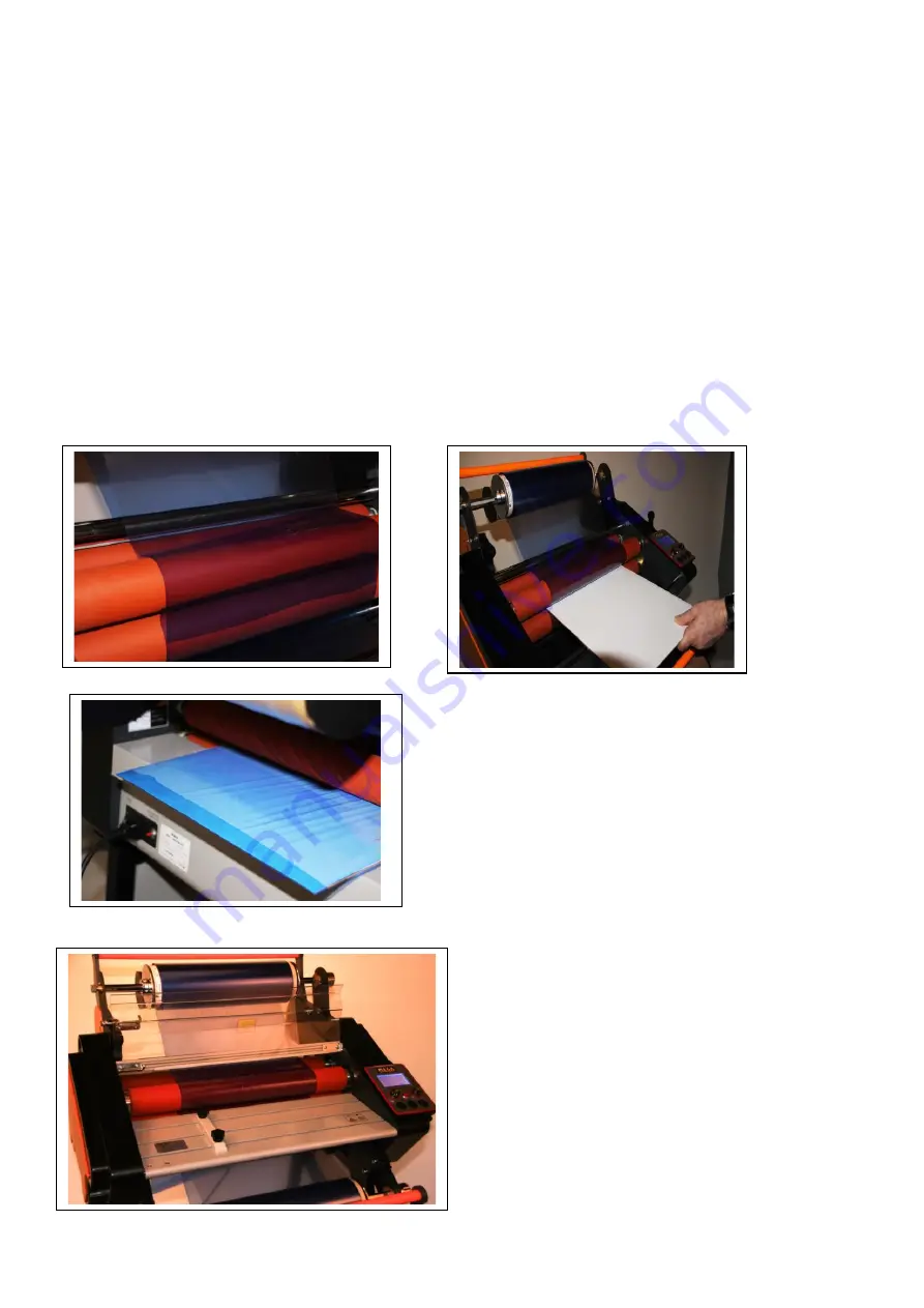
      Using the roller height adjustment and pressure leaver at the right hand side of the 
      laminator open the rollers to the maximum gap and using a piece of card slightly wider 
      than the film and about 200mm in length push the card and two pieces of overlapping film 
      between the rollers. Then push the height adjustment leaver down until it is exerting 
      pressure on the card. 
      Turn on the power and set the Hot/Cold switch to cold and the Stop/Run button to run. Set the 
      speed to 1.4 metres per minute and press and hold down the load button until the card and dry 
      film have pass through the laminator. NB if you need to continue running just the film through the 
      machine you may need to move the leaver further down. 


14. Replace the safety guard and feed tray and your laminator is ready to use. 


Finished loaded laminator. 


Содержание 22-22812-1

Страница 1: ...onics Limited Mega House Grip Industrial Estate Linton Cambridge England CB21 4XN Tel 44 0 1223 893900 Fax 44 0 1223 893894 Email sales megauk com Web www megauk com Part Nos 22 22813 1 18 22 22812 1...

Страница 2: ...er on Safety Precautions Do not use the machine if the power cord is damaged in anyway Do not use a a power supply that is not in accordance with the rated voltage Do not try to disassemble modify or...

Страница 3: ...trol panel Feed tray Bottom stabiliser bar Bottom drip tray Top film take up roller shaft with cardboard tube core support plates Top stabiliser bar Safety cover and Bottom bolt Feed guide Top drip tr...

Страница 4: ...ctivate to prevent the machine getting any hotter Approximate temperature guide This chart is a rough guide only and should NOT be taken as an exact indication of the settings for your laminating job...

Страница 5: ...ssing the load button the rollers will operate while the button is pressed to enable the film to be fed into the machine Operating instructions Check the power voltage for the machine to ensure this m...

Страница 6: ...for the 18 laminator and 650 mm for the 24 laminator The dry film photo emulsion is sandwiched between a polyester cover sheet and a peelable polyolefin sheet The laminator removes the polyolefin cov...

Страница 7: ...a Top drip tray This is fitted by tilting the tray at an angle and sliding it into position b Bottom drip tray This is fitted into place by sliding it into the two bottom drip tray fixing slots A buc...

Страница 8: ...roll core up against the support plate with the loose end of the film hanging at the back of the roll and then replace the support plate you have removed and push it into the other core end as far as...

Страница 9: ...f tape away from each other and the polyolefin protective film will pull away from the surface of the dry film resist coating Pull the polyolefin sheet away and pass it over the top of the dry film ro...

Страница 10: ...de or scissors Using the roller height adjustment and pressure leaver at the right hand side of the laminator open the rollers to the maximum gap and using a piece of card slightly wider than the film...

Отзывы: