background image

22

Source Selection

The default Source Select for the MDLP1 Projector is the 

COMPonent 1 Input. There is an additional Component 

Video Input (COMP 2) along with two HDMI Inputs. 

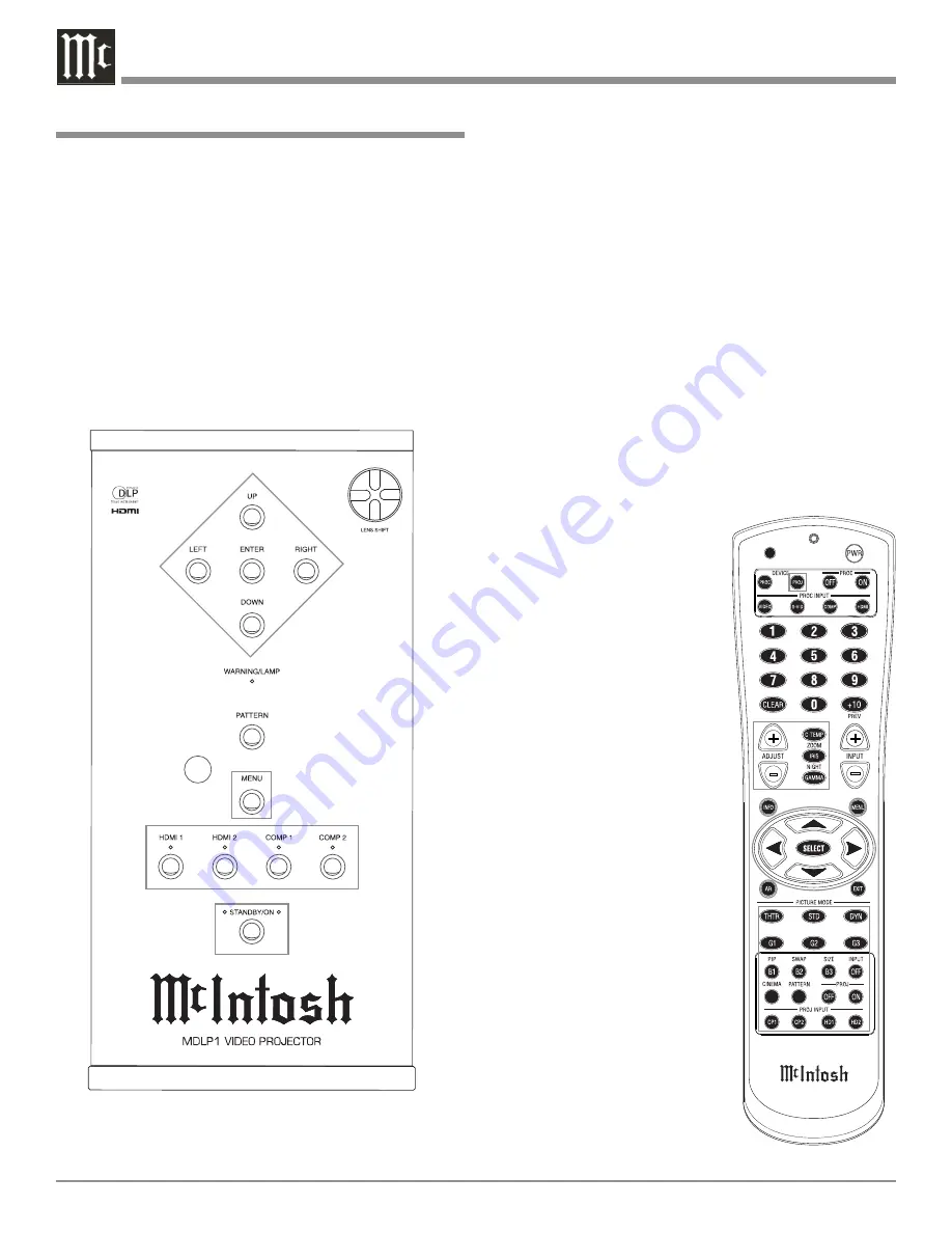
Select the desired source using the push-buttons located on 

the Projector Control Panel or on the PROJ INPUT Push-

buttons located on the Remote Control. Refer to figures 14 

and 15.

Note: Whenever possible use HDMI connections between 

the source device output to the MDLP1 Input. This 

will yield better image quality, as the video signal 

will go through one less analog to digital conver-

sion process and possibly one less digital to analog 

conversion process as well.

Image Adjustments and Setting changes

All of the electronic based image adjustments and pro-

cessing settings are performed by using the extensive 

On-Screen Menuing System. The 

On-Screen Menuing System is in-

teractive and the ability to change 

a given setting is dependent on 

the Input selected, the presence 

of a video signal for that input, 

the Picture Mode selected and are 

automatically saved for the cur-

rently selected video input. When 

a menu item is “grayed out” it 

can not be changed until either 

another Input is selected, a signal 

is present or a different Picture 

mode is selected.

The selection of a menu item 

and the available choices/adjust-

ments are performed by using the 

Navigation (◄LEFT, ►RIGHT, 

▲UP or ▼DOWN) Push-buttons 

along with the ENTER/SELECT 

Push-buttons located on the Pro-

jector Control Panel and/or using 

the Remote Control Push-buttons.

The following examples 

will illustrate how to use the 

On-Screen Menuing System by 

performing the Display Installa-

tion Orientation, Display Vertical 

Keystone Adjustment and Remote 

Control Configuration. All of the 

remaining menu options are per-

formed in a similar manner.

How to Operate the MDLP1

Power

The Red LED to the left of the STANDBY/ON Push-but-

ton lights to indicate the MDLP1 is in Standby mode. To 

Switch ON the MDLP1, press the STANDBY/ON Push-

button on the Projector Control Panel or the Projector ON 

Push-button using the Remote Control. The Green LED to 

the right of the STANDBY/ON Push-button lights to indi-

cate the MDLP1 is ON. Refer to figures 14 and 15.

Notes: 1. It is normal for the projector lamp warm up period 

to last about a minute before an image appears on 

the screen.

2. If the Initial Setup for the MDLP1 has not yet been 

performed refer to page 14 at this time.

Figure 14

Figure 15

Содержание MDLP1

Страница 1: ...McIntosh Laboratory Inc 2 Chambers Street Binghamton New York 13903 2699 Phone 607 723 3512 FAX 607 724 0549 MDLP1 Owner s Manual Video Projector ...

Страница 2: ...rvicing instructions in the litera ture accompanying the appliance WARNING TO REDUCE RISK OF FIRE OR ELECTRICAL SHOCK DO NOT EXPOSE THIS EQUIPMENT TO RAIN OR MOISTURE NO USER SERVICEABLE PARTS INSIDE REFER SERVICING TO QUALIFIED PERSONNEL To prevent the risk of electric shock do not remove cover or back No user serviceable parts inside IMPORTANT SAFETY INSTRUCTIONS PLEASE READ THEM BEFORE OPERATIN...

Страница 3: ...andle the lamp with care In the event of serious trouble call a McIntosh Authorized Dealer 1a Do not directly expose skin to the light of the lamp as it can cause inflamation 2b Do not drop impact subject to excessive force or otherwise damage the lamp 3c Replacing the lamp runs the risk of burns cuts and electric shock unplug the AC power cord from the AC power outlet and wait at least 60 minutes...

Страница 4: ...for all McIntosh products at McIntosh Laboratory Inc 2 Chambers Street Binghamton New York 13903 Phone 607 723 1545 Fax 607 724 0549 Customer Service If it is determined that your McIntosh product is in need of repair you can return it to your Dealer You can also return it to the McIntosh Laboratory Service Department For assistance on factory repair return procedure contact the McIntosh Service D...

Страница 5: ...ion screen See your McIntosh Dealer for additional information 6 The IR Input with 1 8 inch mini phone jack is config ured for non McIntosh IR sensors such as a Xantech Model 291 80 or equivalent To avoid possible interac tion the MDLP1 Sensors may be disabled by activat ing the On Screen Menu then select from the menu Config Remote Control Wired Then deactivate the On Screen Menu Refer to the How...

Страница 6: ...r Control Cable Part No 170 202 Six foot shielded 2 conductor with 1 8 inch stereo mini phone plugs on each end Data Port Connectors The MDLP1 Data In Port receives Remote Control Signals from other McIntosh Components A 1 8 inch stereo mini phone plug is used for connection The IR Ports also use a 1 8 inch stereo mini phone plug and allow the connection of other brand IR Receivers to the MDLP1 RS...

Страница 7: ...dividual pixels 1080p and produces images of such high quality it s just like being there Connectors and Cable Information Introduction and Performance Features video source from 480i to 1080p There is a special 1080p direct pixel pass through mode when the MDLP1 Projector is used with the McIntosh VP1000 Video Processor Video Adjustments The MDPL1 allows for complete adjustment of all the im port...

Страница 8: ...to installing the MDLP1 into cabinets 20 1 4 51 44cm 6 3 4 17 15cm Front View of the MDLP1 Rear View of the MDLP1 Side View of the MDLP1 6 1 4 15 88cm 9 1 2 24 13cm Adjustable Height Front Feet 20 1 4 51 44cm 6 3 4 17 15cm 13 33 02cm 17 11 16 44 93cm 13 3 4 34 93cm 1 1 8 3 18cm See Note 1 3 1 4 8 26cm 14 1 8 35 88cm Note 1 The Long Throw Lens deminsion is 1 3 8 3 49cm ...

Страница 9: ...operating life for any electronic instrument Do not install the MDLP1 directly above a heat generating component Refer to fig ures 1 and 2 The MDLP1 is designed to be placed upright on a solid flat surface resting on its three feet with unrestricted air flow around it Allow at least 1 foot 30 48 cm of space between the Primary Warm Air Exit ventilation holes and the nearest wall or obstruction The...

Страница 10: ... the Projector Lens Bottom of Screen Acceptable Projector Mounting Height Projector placed above the floor Projector and 16 9 Screen Mounting Location The illustrations below together with the charts on the adjacent page will help to assure the correct mounting locations for both the projector and the screen CAUTION The MDLP1 Video Projector weight is 40 pounds 18 14 ki lograms When mounting the p...

Страница 11: ... 8 98 1 16 249 1 256 6 16 650 7 372 6 16 945 1 250 635 0 217 14 16 553 5 122 9 16 311 3 321 814 7 465 15 16 1 182 6 Installation con t MDLP1L with Long Throw Lens 16 9 Screen Size 1 77 1 Aspect Ratio Screen Diagonal Screen Width Screen Height Minimum Distance Maximum Distance Inches Centimeters Inches Centimeters Inches Centimeters Inches Centimeters Inches Centimeters 80 203 2 69 12 16 177 1 39 4...

Страница 12: ...d the Projector Lens Bottom of Screen Acceptable Projector Mounting Height Projector placed above the floor Projector and 4 3 Screen Mounting Location The illustrations below together with the charts on the adjacent page will help to assure the correct mounting locations for both the projector and the screen CAUTION The MDLP1 Video Projector weight is 40 pounds 18 14 ki lograms When mounting the p...

Страница 13: ...16 997 2 570 6 16 1 447 6 MDLP1L with Long Throw Lens 4 3 Screen Size 1 33 1 Aspect Ratio Screen Diagonal Screen Width Screen Height Minimum Distance Maximum Distance Inches Centimeters Inches Centimeters Inches Centimeters Inches Centimeters Inches Centimeters 60 152 4 48 121 9 36 91 4 203 13 16 517 4 203 13 16 517 4 70 177 8 56 142 2 42 106 7 157 11 16 400 2 238 4 16 604 7 72 182 9 57 10 16 146 ...

Страница 14: ...possible geometric distortions in the projected image caused by the physical orientation of the MDLP1 Video Projector relative to the screen While there are electronic adjustments to correct for some of these geometric dis tortions the best images will be achieved when minimal electronic adjustments are used After the projector and screen locations have been established refer to the four previous ...

Страница 15: ...s the STAND BY ON Push button on the Projector Control Panel or the PROJ ON Push button using the Remote Control 16 Temporarily place the previously removed protective cover onto the projector lens 17 Remove the AC Power Cord from the projector 18 Proceed to the How to connect the MDLP1 on page 17 centered vertically on the screen the Crosshatch Test Pattern lines are again white in color 9 Using ...

Страница 16: ...GER 1 Output sends a Turn On signal to other components when the MDLP1 is switched On DATA IN Port receives signals from McIntosh A V Control Center for Remote Control Operation TRIGGER 2 Output sends Turn On signals to other com ponents and may be assigned to activate when a specific as pect ratio is selected POWER CONTROL IN receives turn on signals from a McIntosh compo nent and POWER CON TROL ...

Страница 17: ...ollowing connection 2 Connect a Control Cable from the MDLP1 POWER CONTROL IN A Jack to the McIntosh MX Series Power Control Zone A Out Jack Data Control Connections When the MDLP1 is connected to the McIntosh VP1000 Video Processor no Data Port connection is necessary If the MDLP1 is connected to a McIntosh Audio Video Control Center MX136 MX135 MX120 MX119 MX134 or MX132 MX Series add the follow...

Страница 18: ...t the desired function or option Press to recall various On Screen Information press a second time to deactivate the Menus Press to change the Aspect Ratio of the video image Press to activate the various On Screen Menus press a second time to deactivate the Menus Press to Power ON or OFF the MDLP1 Used to change the Color Temperature settings Used to change the Lens Iris opening size Press to sel...

Страница 19: ... OFF to switch the power Off to the MDLP1 Adjust Functions After menu functions displaying a horizontal adjust ment bar on the screen have been selected such as Image Brightness the ADJUST or ADJUST push buttons may be used to vary the brightness of the image Color Temperature Allows for changing on the fly1 the color neutrality of the image from warm thru cool six different settings Iris Allows f...

Страница 20: ...e settings Power ON Indicator Activates the On Screen Cross Hatch Video Test Pattern Indicates when the projector lamp has failed or if one of the safety functions has been acivated Used to navigate up down to the left and to the right through the various menus Also used to select the desired function or option Allows the Projec tor Lens assembly to be raised or lowered vertically for center ing t...

Страница 21: ...nce Gain 0 26 Chroma Delay 0 26 Input Signal Component 1 Auto 27 Component 2 Auto 27 HDMI 1 Auto 27 HDMI 2 Auto 27 CSC HDMI 1 Auto 27 CSC HDMI 2 Auto 27 MENU FUNCTION SETTING PAGE RGB HD Adjust Mode Auto 27 Readjust 27 Resolution H 0 27 Resolution V 0 27 Position H 0 27 Position V 0 27 Phase 0 27 Clamp Position 0 27 Clamp Width 0 27 Display Keystone 0 23 Scale 0 27 Width 0 27 Position H 0 27 Posit...

Страница 22: ...d out it can not be changed until either another Input is selected a signal is present or a different Picture mode is selected The selection of a menu item and the available choices adjust ments are performed by using the Navigation LEFT RIGHT UP or DOWN Push buttons along with the ENTER SELECT Push buttons located on the Pro jector Control Panel and or using the Remote Control Push buttons The fo...

Страница 23: ...el or on the Remote Control Refer to figures 14 and 15 2 Using the Navigation UP or DOWN Push button select DISPLAY from the Main Menu choices Refer to figure 16 3 Using the Navigation RIGHT push button plus the UP or DOWN Push button select INSTALLA TION from the Display Menu choices 4 Press the Navigation RIGHT push button plus the UP or DOWN Push button select the correct orientation of the pro...

Страница 24: ...rom the Config Menu choices 4 Press the Navigation RIGHT push button and the On Screen Display changes to show a window Refer to figure 22 5 Press the LEFT or RIGHT Navigation push button to select YES to disable the enternal sensors or NO to activate the internal sensors 6 In order to activate the sensor choice it is necessary to press the ENTER Push button on the Control Panel Note The SELECT Pu...

Страница 25: ...Lamp Mode Color Temp Normal A Iris F6 0 Aspect Full Picture Adjust Fine Menu 1 Fine Menu 2 Input Signal RGB HD Adjust Display OSD Blanking Config Full Normal Zoom V Stretch Through Figure 25 ASPECT RATIO OPTIONS 16 9 VIDEO SOURCE 4 3 VIDEO SOURCE MODE IMAGE DECRIPTION IMAGE DECRIPTION INPUT SIGNAL HDMI 1080p signal The Image Source Aspect Ratio is 1 78 1 The Image Source Aspect Ratio is 1 33 1 FUL...

Страница 26: ...Frame Rate Conversion function is basically off However FRC turns on automatically de pending on vertical frequency of input signal On Frame Rate Conversion function is On 60Hz fixed CEC On Chroma Error Correction reduces CUE Chro ma Up sampling Error of 1080i signals Off Normally use this mode Picture Shift V When Aspect on the Picture Adjust menu is set to Zoom this setting allows the user to mo...

Страница 27: ...igure 30 Note Before using the electronic adjustments make sure all of the Initial Setup Mechanical Adjustments have been made first Refer to pages 14 and 15 Keystone Refer to Vertical Keystone Adjustment on page 23 Scale Reduces the image size without changing the aspect ratio The image can be reduced to about 70 of the original size Width Reduces the image width without changing the image height...

Страница 28: ...so settings dealing with the MDLP1 Projection Lamp Refer to figure 32 and your McIntosh Dealer for additional information and or assistance Auto Power Off This feature allows for the MDLP1 to be switched Off automatically 10 minutes after there is a loss of a video signal on the currently selected input thus con serving the projectors lamp life Enable This setting will activate the feature Approxi...

Страница 29: ...with approxi mately 5 hours remaining Refer to figure 36 Finally the last warning message will appear On Screen the MDLP1 Projector will shut Off and the Control Panel WARNING LAMP LED will illuminate red Refer to figure 37 After your McIntosh Dealer has replaced the Projector Lamp check to make sure the Lamp Life has been reset by pressing the INFO Push button on the Remote Control The On Screen ...

Страница 30: ...extended Depth is 18 13 16 inches 47 78cm medium throw lens Depth is 19 1 16 inches 48 41cm long throw lens Weight 40 pounds 18 14 kg net 54 pounds 24 5 kg in shipping carton Shipping Carton Dimensions Width is 32 inches 81 28cm Depth is 28 inches 71 12cm Height is 13 inches 33 02cm Video Inputs 2 Component Analog Video Y Pb Pr 2 HDMI Digital Video 1 1 Compliant McIntosh Data Control Input 1 1 8 i...

Страница 31: ... condition If a shipping carton or any of the interior part s are needed please call or write the Customer Service Department of McIntosh Laboratory Refer to page 4 Please see the Part List for the correct part numbers CAUTION To prevent possible damage to the Projec tor Lens Assembly DO NOT at any time attempt to LIFT CARRY or RE ORI ENT the Projector using the Lens Quantity Part Number Descripti...

Страница 32: ...of its products is the policy of McIntosh Laboratory Incorporated who reserve the right to improve design without notice Printed in the U S A McIntosh Laboratory Inc 2 Chambers Street Binghamton NY 13903 McIntosh Part No 04101000 ...

Отзывы: