background image

17

How to Operate in Four or Three Channel Mode

How to Operate in Four Channel Mode

How to Operate in Three Channel Mode

In the 4 Channel Operating Mode channel pairs of (1 and
2) and (3 and 4) are bridged to provide 200 watts each.
Channels 5 and 6 are driven independently for 100 watts
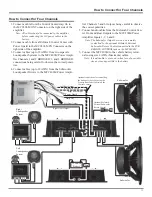
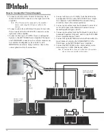
output for each channel. Refer to figures 8 and 9, along
with page 11 of this Owner’s Manual.

Input Source

Set the Channel 3-4 INPUT SOURCE Switch to the 3, 4
and the Channel 5-6 INPUT SOURCE Switch to the 5, 6
position for 4 Channel Mode.

Sensitivity Controls

The Sensitivity Controls (1, 3, 5 and 6) allow setting the
input level of the amplifier channels to provide an ideal
match for the signal source being used.

Note: Set CH2 and CH4  SENSITIVITY Controls to the

maximum counterclockwise position.

Output Mode

Set CHANNELS 1-2 and 3-4 OUTPUT MODE Switches
to the BRIDGED position. Set CHANNELS 5-6 OUTPUT
MODE Switch to the STEREO position. This will config-
ure the amplifier for four channel operation.

High Pass Filter

Set the Channels 1-2 and 3-4 High Pass Filters’ FRE-
QUENCY Control to 100 and the MULTIPLIER Switch to
X1. Set the channel 5-6 High Pass Filter Frequency Control
to 50 and the MULTIPLIER Switch to X.1. This will send
frequencies above 100Hz to the upper range speakers for
channels 1 thru 4 and roll-off frequencies below 5Hz for
channels 5-6.

Low Pass Filter

Set the Channel 3-4 low pass filter to OUT. Set the Chan-
nel 5-6 Low Pass Filter FREQUENCY Control to 100 and
the MULTIPLIER Switch to X1. This will roll-off frequen-
cies above 100Hz for channels 5-6.

In the 3 Channel Operating Mode channel pairs of (1 and
2), (3 and 4) and (5-6) are bridged. This configuration pro-
vides two 200 watt channel amplifiers and one 400 watt
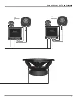
amplifier. Refer to figures 8 and 9, along with pages 12 and
13 of this Owner’s Manual.

Input Source

Set the Channel 3-4 INPUT SOURCE Switch to the 3, 4
and the Channel 5-6 INPUT SOURCE Switch to the 1-4
(SUB) position.

Sensitivity Controls

The Sensitivity Controls allow setting the input level of
amplifier channels 1 and 3 to provide an ideal match for
the signal source being used. Sensitivity Control 5 adjusts
the woofer level balance.

Note: Set CH2, CH4 and CH6 SENSITIVITY Controls to the

maximum counterclockwise position.

Output Mode

Set all three OUTPUT MODE Switches to the BRIDGED
position.

High Pass Filter

Set the Channels 1-2 and 3-4 High Pass Filters’ FRE-
QUENCY Control to 100 and the MULTIPLIER Switch to
X1. Set the channel 5-6 High Pass Filter Frequency Control
to 50 and the MULTIPLIER Switch to X.1. This will send
frequencies above 100Hz to the upper range speakers for
channels 1 thru 4 and roll-off frequencies below 5Hz for
channels 5-6.

Low Pass Filter

Set the Channel 3-4 low pass filter to OUT. Set the Chan-
nel 5-6 Low Pass Filter FREQUENCY Control to 100 and
the MULTIPLIER Switch to X1. This will roll-off frequen-
cies above 100Hz for channels 5-6.

Figure 9

Содержание MCC406M

Страница 1: ...MCC406M Owner s Manual McIntosh Laboratory Inc 2 Chambers Street Binghamton New York 13903 2699 Phone 607 723 3512 FAX 607 724 0549 Power Amplifier ...

Страница 2: ...not install near any heat sources such as radiators heat ducts or other apparatus including amplifiers that produce heat 9 Warning This unit is capable of producing high sound pressure levels Continued exposure to high sound pressure levels can cause permanent hearing impairment or loss User caution is advised and ear protection is recommended when playing at high volumes 10 Route DC power cords s...

Страница 3: ...ct the McIntosh Service Department at McIntosh Laboratory Inc 2 Chambers Street Binghamton New York 13903 Phone 607 723 3515 Fax 607 723 1917 If at any time you have questions about your McIntosh product contact your McIntosh Dealer who is familiar with your McIntosh equipment and any other brands that may be part of your system If you or your Dealer wish addi tional help concerning a suspected pr...

Страница 4: ...n is sonically transparent and absolutely accurate The McIntosh Sound is The Sound of the Music Itself NEGATIVE SPEAKER OUTPUT POSITIVE SPEAKER OUTPUT High Current Output A peak output current of 20 amperes ensures that the MCC406M will successfully drive high quality Loud speakers such as McIntosh for a truly exciting sound ex perience Variable Crossover Filters The 12dB per octave high pass filt...

Страница 5: ...M There is additional in formation on the next page pertaining to installing the MCC406M into your vehicle Dimensions 18 3 8 46 66cm Top View of the MCC406M Side View of the MCC406M 3 3 16 8 09cm 9 3 16 23 33cm 15 3 16 38 57cm 11 13 16 29 97cm 12 1 4 31 12cm 2 15 16 7 49cm 11 27 93cm 11 32 10 93cm ...

Страница 6: ...ly or horizontally and may be located under a seat if adequate clearance is available The preferred installation method is to mount the amplifier directly to the vehicle main frame using the hard ware supplied with the amplifier It is not recommended that the amplifier be mounted under the hood or in a location where it will be directly ex posed to the elements The openings in the fan housings and...

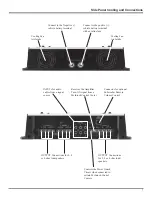
Страница 7: ...ntrols the Power Guard Circuit when connected to certain McIntosh Control Centers Cooling Fan Air Intake OUTPUT Connections for 2 4 or 8 ohm loud speakers Receives the Amplifier Turn ON signal from a McIntosh Control Center Connect to the Negative vehicle battery terminal OUTPUT Connections for 2 4 or 8 ohm loudspeakers Connector for optional Subwoofer Remote Volume Control ...

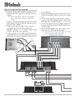
Страница 8: ...nnect a cable up to 12 AWG from the Subwoofer Loudspeaker Driver to the McIntosh Mono Power Am plifier Output Terminals being careful to observe the correct polarities 5 Connect audio cables from the Control Center Front Outputs to the McIntosh Electronic Crossover Inputs 1 and 2 6 Connect audio cables from the McIntosh Electronic Crossover Low Mid and High Outputs 1 and 2 to the MCC406M Power Amp...

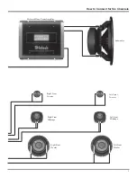
Страница 9: ...9 How to Connect for Six Channels Left Front Tweeter Left Front Midrange Left Front Woofer Right Front Tweeter Right Front Midrange Right Front Woofer Subwoofer McIntosh Mono Power Amplifier ...

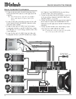
Страница 10: ...to 12 AWG from the Subwoofer Loudspeaker Drivers to the MCC406M Power Ampli fier Channels 5 and 6 BRIDGED connection being careful to observe the correct polarities 5 Connect audio cables from the McIntosh Control Cen ter Front and Rear Outputs to the MCC406M Power Amplifier Inputs 1 2 3 and 4 6 Connect the optional McIntosh external Subwoofer Re mote Volume Control to the SUB REMOTE CON TROL Jack...

Страница 11: ...s 5 and 6 Outputs being careful to observe the correct polarities 5 Connect audio cables from the McIntosh Control Cen ter Front and Rear Outputs to the MCC406M Power Amplifier Inputs 1 2 3 and 4 Note The Subwoofer Output Level can be remotely controlled by the optional McIntosh External Subwoofer Rotary Control connected to the SUB REMOTE CONTROL jack on the MCC406M 6 Connect the MCC406M to the v...

Страница 12: ...t Power Guard Amp ON Vehicle Battery Fuse McIntosh External Subwoofer Rotary Control 4 Connect cables up to 12 AWG from the Subwoofer Loudspeaker Drivers to the MCC406M Power Ampli fier Channels 5 and 6 BRIDGED connection being careful to observe the correct polarities 5 Connect audio cables from the McIntosh Control Cen ter Front Outputs to the McIntosh Custom Environ mental Equalizer Inputs 1 an...

Страница 13: ...13 How to Connect for Three Channels Left Loudspeaker System Right Loudspeaker System Subwoofer ...

Страница 14: ...ter Switch and Control select the low frequency roll off or flat frequency response CH 1 2 HIGH PASS Filter Switch and Control select the low frequency roll off or flat frequency response CH 5 6 SENSITIVITY Individual Input Sensitiv ity Controls for Channels 5 and 6 INPUT SOURCE Switch for Channels 5 6 selects either CHs 5 and 6 1 and 2 or Subwoofer Sum of CHs 1 2 3 and 4 POWER GUARD LED lights wh...

Страница 15: ...tting the FREQUENCY Control to 150 and the MULTIPLIER Switch to X 1 150 times 1 equals 15 Input Sensitivity Controls The SENSITIVITY controls allow independent setting of the input sensitivity of all amplifier channels to provide an ideal match for the signal source being used The most de sirable setting allows the control center to have a useful volume range as wide as possible from loud to soft ...

Страница 16: ...s Filter Switches to the OUT posi tion In the 5 Channel Operating Mode channels 1 thru 4 oper ate as independent 50 watt amplifiers for the front and rear Loudspeakers channels 5 and 6 are Bridged for 400 watts of power output Refer to figures 8 and 9 along with page 10 of this Owner s Manual Input Source Set the Channel 3 4 INPUT SOURCE Switch to 3 4 and the Channel 5 6 INPUT SOURCE Switch to the...

Страница 17: ...ss Filter Set the Channel 3 4 low pass filter to OUT Set the Chan nel 5 6 Low Pass Filter FREQUENCY Control to 100 and the MULTIPLIER Switch to X1 This will roll off frequen cies above 100Hz for channels 5 6 In the 3 Channel Operating Mode channel pairs of 1 and 2 3 and 4 and 5 6 are bridged This configuration pro vides two 200 watt channel amplifiers and one 400 watt amplifier Refer to figures 8 ...

Страница 18: ...ace remove the suction cup and save it for future use 4 Remove the Phillips Screws holding the End Caps on both sides of the amplifier and lift the end caps off 5 Remove the two Phillips screws located between the low and high pass filter controls 6 Remove all 12 crossover equalizer and sensitivity knobs 7 Remove the Gold Faceplate Control Panel 8 Remove the fuses with needle nose pliers taking ca...

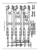
Страница 19: ...19 MCC406M Block Diagram MCC406M Block Diagram ...

Страница 20: ...20 ...

Страница 21: ...21 Notes ...

Страница 22: ... Bridged Mode with 4 ohm loads Dynamic Headroom 1dB Frequency Response 0 0 25dB from 20Hz to 20 000Hz 0 3dB from 10Hz to 50 000Hz Sensitivity 0 5Volts A Weighted Signal To Noise Ratio 105dB 1 5V High Pass Filter Variable from 5Hz to 5 000Hz 12 dB per octave Low Pass Filter Variable from 50Hz to 5 000Hz 12 dB per octave 24 dB per octave in Bridged Mode for Channels 5 and 6 Subwoofer Filter Low Pass...

Страница 23: ...below failure to do so will result in shipping damage Make sure that the Top Glass Panel is firmly secured to the chassis using the supplied hex head screws Use the original shipping carton and interior parts only if they are all in good serviceable condition If a shipping carton or any of the interior part s are needed please call or write Customer Service Department of McIntosh Labo ratory Pleas...

Страница 24: ...Chambers Street Binghamton NY 13903 The continuous improvement of its products is the policy of McIntosh Laboratory Incorporated who reserve the right to improve design without notice Printed in the U S A McIntosh Part No 040842 ...

Отзывы: