14
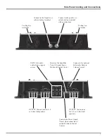
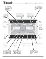
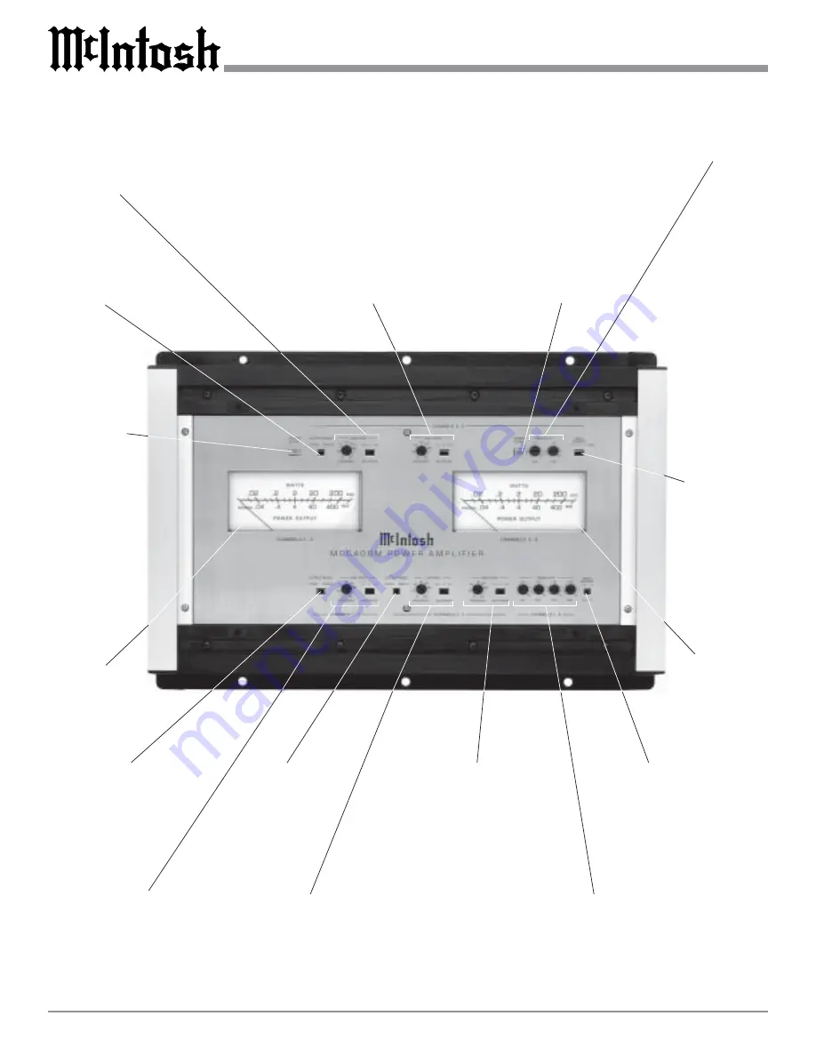
Top Panel Controls, Display and Switches
METER
indicates
Channels
1 thru 4
Power
Output
POWER
GUARD LED
lights when the
Power Guard
Circuit acti-
vates for Am-
plifier Channels
1 thru 4
METER
indicates
Channels
5 and 6
Power
Output
CH 5-6 MODE Switch
selects STEREO or
BRIDGED mode of
operation
CH 1-2 MODE
Switch selects
STEREO or
BRIDGED mode
of operation
CH 5-6 LOW PASS
Filter Switch and Con-
trol select the high fre-
quency roll-off or flat
frequency response
CH 3-4 LOW PASS Filter
Switch and Control select
the high frequency roll-off
or flat frequency response
CH 5-6 HIGH PASS Filter
Switch and Control select
the low frequency roll-off
or flat frequency response
CH 1-2 HIGH PASS Filter
Switch and Control select
the low frequency roll-off
or flat frequency response
CH 5-6 SENSITIVITY
Individual Input Sensitiv-
ity Controls for Channels
5 and 6
INPUT
SOURCE
Switch for
Channels 5-6
selects either
CHs 5 and 6,
1 and 2 or
Subwoofer
(Sum of CHs
1, 2, 3, and 4)
POWER GUARD LED
lights when the Power
Guard Circuit activates
for Amplifier Channels
5 or 6
CH 1-4 SENSITIVITY
Individual Input Sensitivity
Controls for Channels 1, 2,
3 and 4
CH 3-4 MODE
Switch selects
STEREO or
BRIDGED mode
of operation
CH 3-4 HIGH PASS Filter
Switch and Control select
the low frequency roll-off
or flat frequency response
INPUT SOURCE Switch
for Channels 3-4 selects
either CHs 3 and 4 or 1
and 2
Содержание MCC406M
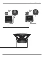
Страница 13: ...13 How to Connect for Three Channels Left Loudspeaker System Right Loudspeaker System Subwoofer ...
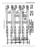
Страница 19: ...19 MCC406M Block Diagram MCC406M Block Diagram ...
Страница 20: ...20 ...
Страница 21: ...21 Notes ...

