


MBNLED
DMX STRIP 30
www.mbnled.com
11
Contents
1. Hardware Setup ………………………………………………………………..……. 11
2. Operation of up to 8 Strips ………………………………………………………... 13
3. Operation of more than 8 Strips with AUX Power Input ….…..……………… 14
4. Inbetriebnahme und Software Setup …………………………………………….. 17
5. Fehlerbeseitigung …………..……………………………………………………….. 19
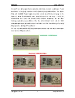
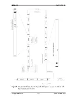
1. Hardware setup of the Strips
The following figures show the layout of each side of the strips and the main
functional parts which will be referred in the manual by numbers in brackets (e.g. [2])
Figure 1.
Backside view of the LED Strip
1. Input connector (white) for +24V DC and DMX signal
2. Power bridge (see later in the AUX power using section)
3. AUX Power input terminal (see later in the AUX power using section)
4. Output connector (dark grey) for +24V DC and DMX signal


