Chapter 2 Wiring
30
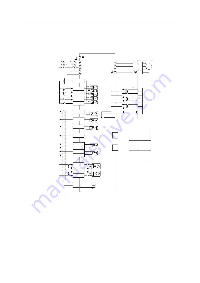
2.7 Standard wiring diagram
2.7.1 Standard wiring diagram
3 phase
AC 220V
QF
KM
L1
L2
L3
L1C
L2C
DC
12~24V
FG
X1 Metal Shell
X1
X2
Servo Drive
Servo
motor
DO 1
4
DO 2
17
DO 3
5
COM+
1
DI 1
14
DI 2
2
DI 3
15
DI 4
3
DI 5
16
U
V
W
Encoder
Connector
Servo motor
power
connector
(4 core)
HDI1+
20
HDI1-
7
HDI2+
19
HDI2-
6
4
5V
5
0V
1
SD+
2
SD-
3
E+
8
E-
9
FG
X1
X1
11
DO4+
23
DO4-
12
DO5+
24
DO5-
X1
DO
COM
18
X2 Metal
Shell
DO Public
Terminal
CCW Drive Inhibition
CCWL
HOME SWITCH
CW Drive Inhibition
CWL
magnetic brake
BRK
2k
Ω
U
V
W
75
Ω
2k
Ω
75
Ω
4.7k
Ω
Note 1: The DI/DO port function of X1
terminal is programable by software
.This picture shows factory default
setting, which can meet general
purpose . Customers can change it
as required.
Note 2: The X2 terminal is the
encoder interface, which is different
according to the encoder type. For
specific connection, please refer to
section 2.3.2.
DO Output
User defined function
X5
X6
EtherCAT controller
or
Last EtherCAT slave
station
Next
EtherCAT slave
station
Position high
speed latch
DO Output
User defined function
DI Input
User defined function
Note: The above wiring diagram is an example of GL7A5.
Содержание EP3E Series
Страница 10: ......


