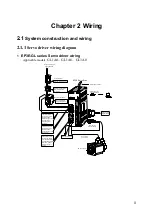
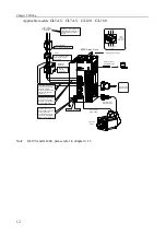

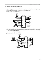


2.1 System construction and wiring
15
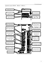
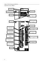
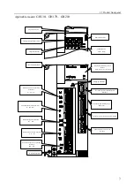
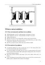
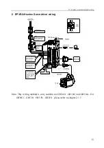
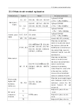
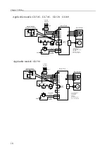
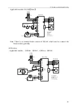
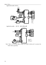
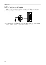
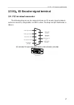
2.1.4
Main circuit terminal explanation
Terminal name
Symbol
Model
Detailed explanation
Main power
supply
L1
、
L2
GL1A0
、
GL1A8
、
GL3A0
1 phase 220VAC
-15%
~
+10% 50/60Hz
L1
、
L2
、
L3
GL5A5
、
GL7A5
、
GL120
、
GL160
、
GL190
、
GL240
3 phase 220VAC
-15%
~
+10% 50/60Hz
GH series
3 phase 380VAC
-15%
~
+10% 50/60Hz
Control power
supply
L1C
、
L2C GL series
1 phase 220VAC
-15%
~
+10% 50/60Hz
24V
、
0V GH series
Connect DC 24V externally
Brake resistor
P
、
B1
、
B2
GL1A0
【
Note 1
】、
GL1A8
、
GL3A0
、
GL5A5
、
GL7A5
、
GL120
、
GL160
、
GH2A0
、
GH3A5
、
GH5A4
When the external brake
resistor is needed, disconnect
the short wires between B1
and B2 [note 2] and crossover
the external brake resistor to
terminals P and B1. Leave B2
unconnected.
。
NC
、
P
、
B
GL190
、
GL240
【
Note 1
】、
GH8A5
、
GH130
、
GH170
、
GH210
When the external brake
resistor is needed, it must
disconnect the internal brake
resistor wire between
terminals P and B firstly,
connect those two wires to NC
at the same time, and then
crossover the external brake
resistor to terminals P and B.
Power supply
higher order
harmonics
restrain-use
N1
、
N2
GL190
、
GL240
、
GH series
When the power supply higher
order harmonics needs to be
restrained, connect the DC
reactor
between
N1
and
N2[note 2]
DC reactor
connection
terminals
U
EP3E series
Output to U phase of servo
motor
V
Output to V phase of servo
motor
W
Output to W phase of servo
Содержание EP3E Series
Страница 10: ......


