


Chapter 2 Wiring
26
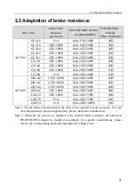
2.
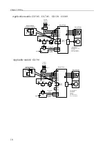
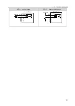
Digital output interfaces (C2)
The digital outputs use Darlington photo-coupler. It can be connected with relay,
photo-coupler. Please notic the following
:
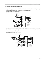
Inverting the polarity of DC power source, which is provided by the user, can cause the servo
driver damage.
The maximum voltage of external DC power supply is 25V, the maximum output current is
50mA, and the total current for three channels is not in excess of 100mA.
When using relay like inductive loads, a free-wheel diode must be connected with the
inductive load in parallel. If the diode connects in wrong direction can cause damage to the
output circuit.
Owing to the low level of output is approximately 1V and cannot satisfy the TTL low-level
request, therefore cannot directly connect with the TTL circuit.
C2-1
:
Relay
C2-2
:
Photo coupler
Servo Drive
DC5V~24V
Relay
DO1
DO2
DO3
4
17
5
0V
DOCOM
24
Max. 50mA
output
DO4+
DO4-
DO5+
DO5-
23
12
11
18
Servo Drive
DC5V~24V
DOCOM
0V
Max. 50mA
Output
18
DO1
DO2
DO3
4
17
5
24
DO4+
DO4-
DO5+
DO5-
23
12
11
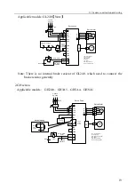
Freewheel diode must be connected.
3. Position high speed latch interface
(
C3
)
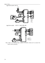
C3
:
Position high speed latch interface
HDI2+
HDI2-
HDI1+
HDI1-
24V
R
R
Servo Drive
2k
Ω
75
Ω
1k
Ω
2k
Ω
75
Ω
1k
Ω
20
7
19
6
HDI2+
HDI2-
HDI1+
HDI1-
24V
R
R
Servo Drive
2k
Ω
75
Ω
1k
Ω
2k
Ω
75
Ω
1k
Ω
20
7
19
6
Maximum pulse frequency 200kHz
;
Содержание EP3E Series
Страница 10: ......


