Copyright 2016
Page
4
of 14
S161222
IV. IMPORTANT THINGS CUSTOMERS MUST KNOW BEFORE ASSEMBLING THIS ARF
1.
This is a large-scale airplane. Sport-aerobatic maneuvers are not recommended. Due to its size,
weight, power, and the number of engines, this airplane is recommended only for advanced-
level builders and pilots. Please read all instructions carefully even if you are an experienced
builder. Any assembling, testing or flying of this airplane is done entirely at your own risk.
2.
Use a receiver battery to power your radio system. Do not use the battery eliminator circuits built into
the ESCs. (NOTE: Our optional custom made 2-conductor 1-to-6 multi-harness is made especially for
this ARF with no red wire so you may connect six ESCs to each harness and each harness to a throttle
port on your receiver. If you do not use our optional custom made 2-conductor 1-to-6 multi-harness
you must ‘open’ the red wire in the throttle lead of each of the twelve electronic speed controls.
3.
During early tests we verified the Dornier Do X might fly on only 10 motors without nacelles installed
(only the motor boxes). However, for safety we strongly recommend using 12 motors with a
minimum 25A ESC and 3S LiPo battery for each propeller to minimize the chance of any unexpected
major power loss in the air.
4.
Based on our extensive testing, the Maxford USA 25A ESCs may be located either under the hatch in
the nose (close to the batteries for shorter battery wires) or inside the motor boxes (close to the
motors for better cooling). This ARF comes pre-wired for locating the ESCs in the nacelles for better
cooling. If you prefer to locate the ESCs in the nose you could add one more wire into the wing’s
center section. If you do so, we recommend using 16 AWG silicon wire.
5.
Placing the LiPo flight batteries in the forward section of the fuselage under the nose hatch simplifies
removal of the batteries for recharging. The overall flying weight is also reduced since carrying the
batteries in the nose means little or no extra weight is needed to balance at the recommended CG.
6.
We recommend using 12 stand-alone power systems for this ARF. However, to reduce the number of
batteries to plug in before and after each flight, the customer has the option to use 2 or 4 LiPo batteries
with mAh and C ratings high enough to supply power to 6 or 3 of the motors at the same time.
However, using 2 or 4 LiPo battery packs increases the flying risk: if any battery has a problem, you
will lose all 3 or 6 motors attached to that battery at the same time.
V. STORAGE, FIELD SETUP & PREFLIGHT CHECKS
1.
Check the Mylar covering material’s joints and surfaces. If necessary, carefully use an iron on medium
heat to secure the edges and to tighten any loosened areas. Recheck and retighten from time to time; be
careful to not apply too much heat as you secure edges or tighten the Mylar. If any trim becomes
loosened, press it down and/or apply clear tape. Never apply heat to any trim, insignia, marking or
plastic part. (NOTE: A conservative modeler may wish to carefully apply a thin coat of epoxy to seal all
seams to help protect against water leakage. Do not apply excess heat at the seams where you have
applied epoxy to the Mylar covering material.)
2.
Ensure the propellers are securely attached to your motors and that they remain undamaged and
correctly balanced.
3.
As with all radio-controlled model airplanes, your Dornier Do X must pass the radio-range ground check
recommended by your radio’s manufacturer or you may not fly safely.
4.
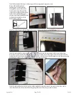
To remove the outer wing panels:
a.
Remove and set aside the bolt that secures each wing panel to the wing’s center section. Slide the
wing panels approx. 2-inches away from the wing’s center section, disconnect the aileron servo
extensions, then slide the wing panels away from the wing’s center section and off the wing rod. The
wing rod may also be removed from the wing’s center section if desired for transport or storage.
Carefully secure the removed screw(s), optional Maxford USA servo-extension safety clips if
installed, and wing rod.
b.
Reverse the above procedure to reattach the wing panels. As each wing panel nears the wing’s
center section, reconnect the aileron servo extensions and optional Maxford USA servo-extension
safety clips, guide the alignment pins into their openings in the outer ribs of the wing’s center
section, slide the tab into its slot, and insert and secure the bolt through the mounting tab and into
the blind nut inside the wing’s center section.


