background image

6-1 

TROUBLESHOOTING 


www.maxcessintl.com 

MAGPOWR DFC-90 

MI 850A265 1 G 


Follower arm applications 

Symptom 

Possible cause 

Solution or diagnostic 

No clutch/brake 
output 
 

No AC power 
 

Verify incoming power is correct voltage and 
frequency. 

Fuses blown 

Clutch/brake wires shorted together or 
shorted to ground. 

Clutch/brake wires open circuit 

Disconnect clutch/brake wires at the DFC-90 
and check for proper clutch/brake resistance 
between the wires. 

Remote tension adjust 
potentiometer turned full 
counter-clockwise or not wired 
properly 
 

Verify tension pot wiring, turn tension adjust 
pot full clockwise and follow the calibration 
procedure beginning on page 4-2. 
Voltage between terminals 20(+) and 22(-) 
should be greater than zero and should 
change as the DFP or DFP-2 is moved through 
its travel. 

Remote tension potentiometer 
resistance is less than 10kΩ 

Use a 10kΩ potentiometer for the Remote 
tension control. 

DFP, DFP-2 position sensor not 
wired properly or wires shorted 

Verify position sensor is wired properly and 
follow the calibration procedure beginning on 
page 4-2. 

Voltage between terminals 24 and 26 should 
be 10 VDC. 

Voltage between terminals 25 and 26 should 
change as the DFP or DFP-2 is moved through 
its travel. 

Follower Arm not calibrated 

Follow the calibration procedure beginning on 
page 4-2. 

Clutch/brake 
output does not 
increase during 
stop time 

RUN/STOP switch not connected 
or not wired properly 

Verify RUN/STOP switch wiring. 

STOP MULTiplier potentiometer 
not set properly 

Turn STOP MULT potentiometer clockwise to 
increase the stopping torque. 

Remote meter not 
working 

Incorrect type of meter 

Meter should be a current meter with 1 mA 
full scale and no more than 3kΩ resistance.  

Meter wires shorted or open 

Disconnect meter wiring at the DFC-90 and 
check for proper meter resistance between the 
wires. 


Содержание MAGPOWR DFC-90

Страница 1: ...MAGPOWR DFC 90 Instruction Manual EN Dancer Follower Arm Control 90VDC MI 850A265 1 G...

Страница 2: ...3 1 FOLLOWER ARM APPLICATIONS 4 1 Electrical connections 4 1 Sensor setup 4 1 Control setup 4 2 Operation 4 4 DANCER APPLICATIONS 5 1 Electrical connections 5 1 Sensor setup 5 2 Dancer control setup...

Страница 3: ...erstanding that it will be retained in confidence and will neither be duplicated nor copied in whole or in part nor be used for any purpose other than for which disclosed Copyright 2011 all rights res...

Страница 4: ...be controlled For best torque control resolution the lowest current range providing sufficient current for maximum operating torque should be selected Connections are provided for an external 1 mADC c...

Страница 5: ...nforced insulation or protective screening which provides protective separation All wiring should comply with the essential requirements of the appropriate standard s and is the responsibility of the...

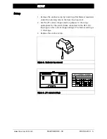
Страница 6: ...er the retaining tabs in the base See Figure 2 2 Set the JP1 current range selection jumpers to the range appropriate for the clutch brake connected to the DFC 90 See Figure 3 for current range settin...

Страница 7: ...remote meter output are not isolated from the AC line and must not be ground referenced The control inputs are isolated and may be ground referenced See Figure 4 Sensor setup The DFP or DFP 2 positio...

Страница 8: ...e follower arm is halfway through its travel Figure 5 Follower arm electrical connections Control setup The control adjustments marked with an underline on the label are the only ones needed for follo...

Страница 9: ...external TENSION pot full clockwise 3 Position the follower arm on an empty core 4 Adjust the CORE pot to obtain zero on the remote meter 5 Adjust the ZERO pot until the meter just starts to increase...

Страница 10: ...ED indicator illuminates when the Stop Time expires Operation Adjust tension with the external 10k tension pot Adjust rewind taper with the FULL pot The tension will decrease as the roll diameter incr...

Страница 11: ...e meter output are not isolated from the AC line and must not be ground referenced The control inputs are isolated and may be ground referenced See Figure 7 Figure 7 Dancer electrical connections INCR...

Страница 12: ...sensor so that its keyway is pointing towards the top cover when the dancer is half way through its travel This is an approximate adjustment and is intended to center the sensor position to allow maxi...

Страница 13: ...ers to the settings given below F switch PD P full clockwise D mid rotation approximately 11 turns CORE full counter clockwise STOP TIME full counter clockwise STOP MULT full counter clockwise 2 With...

Страница 14: ...t clockwise until the oscillation stops The RUN STOP input must be used if the integrator is on switch in PID position The RUN STOP input should be closed terminals 17 and 18 when the machine starts i...

Страница 15: ...een PD PID while the machine is running since this may result in a large transient jump in the output PD mode 1 With a roll diameter near core and the machine stopped set the F switch to PD mode 2 Run...

Страница 16: ...t by the amount necessary to eliminate the overshoot Adjustment is now complete for the dancer operating in PD mode PID mode The next steps complete the tuning of the dancer operating in PID mode 1 Wi...

Страница 17: ...entiometer resistance is less than 10k Use a 10k potentiometer for the Remote tension control DFP DFP 2 position sensor not wired properly or wires shorted Verify position sensor is wired properly and...

Страница 18: ...and 26 should change as the DFP or DFP 2 is moved through its travel Dancer not calibrated Follow the calibration procedure on page 5 3 DFC 90 in PID mode and RUN STOP switch is not wired properly Ve...

Страница 19: ...ion degree 2 IEC664 1 Altitude 0 to 2000 m 0 to 6562 ft Compatible residual current Device types A or B IEC755 Worst case fault current 1 6 A AC Inputs Signal DFP or DFP 2 potentiometer 1 to 10k 1 4 W...

Страница 20: ...Fax 1 405 755 8425 Web www maxcessintl com Fife Tidland GmbH Max Planck Strasse 8 65779 Kelkheim OR Deutschland Telefon 49 6195 7002 0 Fax 49 6195 7002 933 Web www maxcess eu Siemensstrasse 13 15 486...

Отзывы: