


Hi
‐
T
Centralized
controller
7
3
USER
INTERFACE
The
touch
‐
screen
can
be
used
in
the
following
ways:
•
Interface
panel
(unit
interface)
for
a
single
heat
pump
•
Network
controller
for
multi
heat
pump
installation
•
Network
controller
for
multi
heat
pump
and
fan
coil
installation
•
Network
controller
for
multi
fan
coil
installation
To
manage
the
system
modularity,
the
interface
foresees
a
home
page
which
summarizes
the
whole
plant,
showing
dynamically
the
enabled
resources
and
hiding
the
ones
not
available
in
the
current
configuration.
The
interface
also
provides
a
second
summary
page
including
all
the
values
of
temperature
and
humidity
detected
in
the
system.
Through
the
menu
it
is
possible
to
access
to:
•
Plant
configuration
•
Single
units
statuses
•
Zones,
machines
and
plant
settings
As
alternative
it
is
possible
to
directly
access
from
the
home
page
to
detailed
information,
pressing
on
the
display
where
are
located
the
summarized
information.
E.g.,
pressing
where
are
located
the
main
information
of
the
heat
pump,
you
can
enter
in
the
menu
of
the
heat
pump
status.
3.1
ICONS
DISPLAY
All
icons
on
the
different
screens
can
be
shown
in
full
colours
or
de
‐
saturated
as
in
the
following
example:
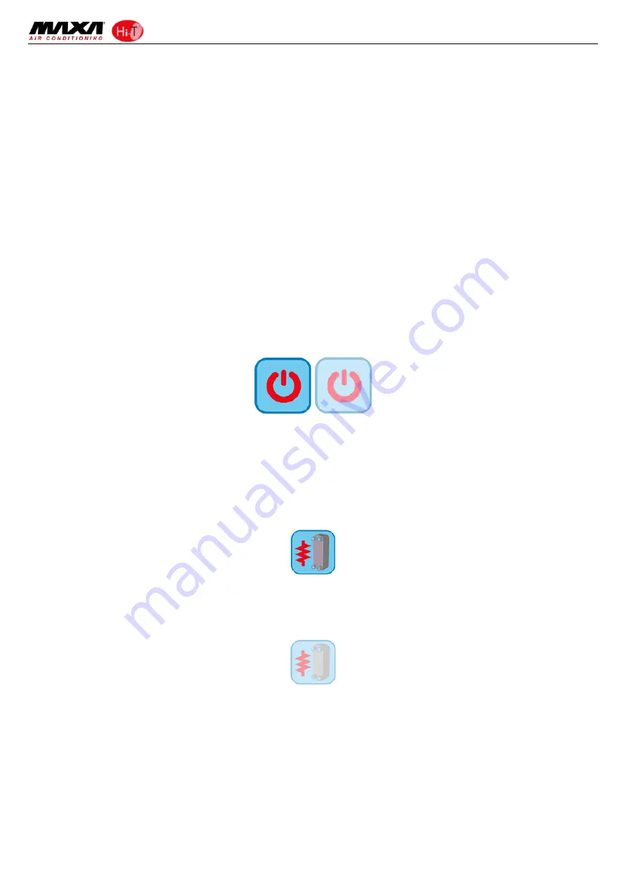
The
colour
saturation
indicates
that
icon
is
usable;
when
pressed
the
related
function
is
performed.
The
transparency
(de
‐
saturated)
indicates
that
icon
is
not
usable
and
any
touch
on
it
has
no
resulting
action.
For
what
concerns
the
side
sliding
bar
which
appears
on
the
left
side
of
the
screen
related
to
the
single
units
connected
into
a
network
(see
Paragraphs
3.4.1.3
e
3.4.2.1),
if
an
icon
appears
fully
coloured
the
related
function
is
enabled
and,
in
that
specific
moment
is
also
active
(i.e.
if
the
“
water
anti
‐
freeze
”
icon
of
the
heat
pump
is
present
and
coloured,
as
shown
below,
the
plate
exchanger
electrical
heating
elements
are
switched
on).
Instead,
if
the
icon
appears
but
is
transparent
(de
‐
saturated),
the
related
function
is
enabled
but
not
that
moment
activated
(i.e.
if
the
“
water
anti
‐
freeze
”
icon
of
the
heat
pump
appears
transparent,
as
shown
below,
the
plate
exchanger
electrical
heating
elements
are
ready
to
work
but
currently
switched
off).
3.2
SCREENS
AND
ICONS
There
might
be
some
differences
between
screens
and
icons
as
they
are
currently
shown.
The
Company
reserves
itself
to
modify
and
update
them
without
prior
notice
and
in
relation
to
what
shown
in
the
present
manual.


