


Hi
‐
T
Centralized
controller
11
9.
Icons
of
the
navigation
sidebar
3.4.1.1
ASSIGNMENT
OF
NAMES
TO
THE
CHILLERS
For
the
assignment
of
the
name
to
a
chiller,
you
must
navigate
between
the
pages
of
the
chiller
connected
to
the
network
until
you
get
to
the
page
of
the
chiller
which
you
want
to
change
the
name:
for
apply
this,
you
have
to
make
single
press
into
the
pressure
sensitive
area
4
.
Once
you
find
the
chiller,
press
and
hold
for
a
few
seconds
in
the
same
area
4.
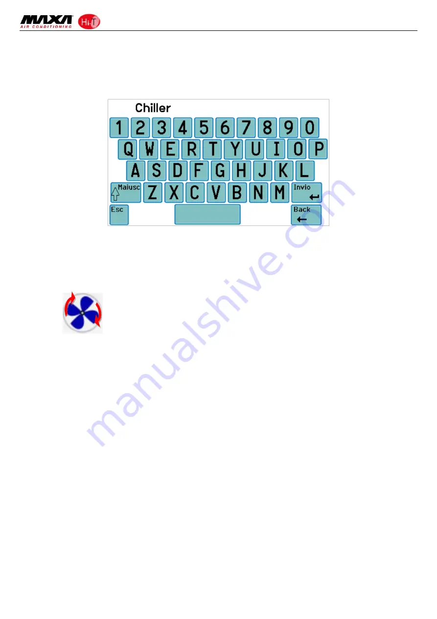
Then
compose
with
the
keyboard
that
appears
the
desired
name.
Figure
11.
Insert
chiller
name.
The
name
of
the
chiller
can
have
a
maximum
of
13
characters.
3.4.1.2
CHILLER
AREA
The
area
5
shown
in
Figure
10
gives
indications
about
the
operation
(compressor
running)
of
the
chiller,
graphically
displaying
the
fan
rotation.
Pushing
down
on
the
area
5
you
access
to
a
further
screen
that
shows
a
list
of
read
data
in
real
time
related
to
the
involved
chiller:
•
Inlet
water
temperature
(°C)
•
Outlet
water
temperature
(°C)
•
Sanitary
probe
temperature
(if
it’s
present
and
configured,
°C).
Accessing
the
same
page
with
service
or
manufacturer
access
right
(to
enable
the
access
right,
press
on
the
“configurations”
icon
present
in
the
sensitive
area
8
of
Figure
10
and
set
the
service/manufacturer
password),
the
data
displayed
in
real
‐
time
are:
•
Inlet
water
temperature
(°C)
•
Outlet
water
temperature
(°C)
•
Sanitary
probe
temperature
(if
it’s
present
and
configured)
•
High
pressure
(bar)
•
Low
pressure
(bar)
•
Compressor
speed
(Hz)
•
Opening
expansion
valve
(step)
•
Fan
speed
(%)
•
Pump
speed
(%)
•
Overheating
(°C)
•
Compressor
operating
hours
(Hr.)
•
Pump
operating
hours
(Hr.)


