


51
9.19 DRIVE AXLE SET REPLACEMENT - CONTINUED
CHAPTER 9: PART REPLACEMENT GUIDE
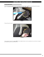
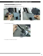
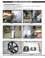
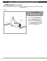
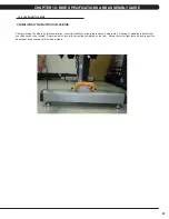
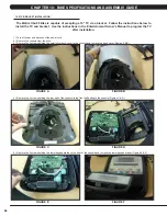
9) Slide the drive axle assembly into the frame from the right side. Install the bearing cap portion of the tool into the left side of the frame (Figure
G).
10) Mount the other tool from Figure F behind the bearing cap portion of the tool. Use the M10 x 100L x 1.25P screw with a nut to attach the tool
to the drive axle (Figure H).
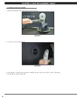
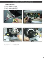
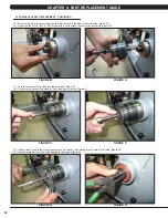
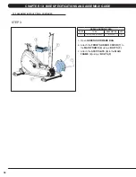
11) Turn the screw until it is close into the drive axle (Figure I).
12) Then turn the nut until it is close to the cup portion of the tool (Figure J).
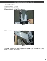
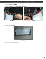
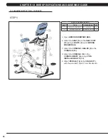
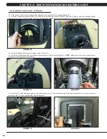
13) Use a wrench to hold the screw, then turn the nut to pull the drive axle into the frame (Figure K).
14) Turn the nut until the iron plate is close to the frame on the right side (Figure L).
FIGURE H
FIGURE G
FIGURE I
FIGURE J
FIGURE L
FIGURE K
Содержание U3X-05
Страница 1: ...U 3 X 0 5 B I K E S E R V I C E M A N U A L...
Страница 4: ...1 1 1 SERIAL NUMBER LOCATION CHAPTER 1 SERIAL NUMBER LOCATION FRAME SERIAL NUMBER LOCATION...
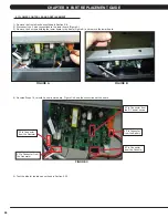
Страница 15: ...12 8 1 ELECTRICAL DIAGRAMS CHAPTER 8 TROUBLESHOOTING...
Страница 16: ...13 8 1 ELECTRICAL DIAGRAM CHAPTER 8 TROUBLESHOOTING...
Страница 17: ...14 8 1 ELECTRICAL DIAGRAMS CONTINUED CHAPTER 8 TROUBLESHOOTING MCB POWER WIRE DIGITAL COMMUNICATION WIRE...
Страница 18: ...15 PULSE SENSOR WIRE RIGHT CHAPTER 8 TROUBLESHOOTING 8 1 ELECTRICAL DIAGRAMS CONTINUED PULSE SENSOR WIRE LEFT...
Страница 19: ...16 8 1 ELECTRICAL DIAGRAMS CONTINUED CHAPTER 8 TROUBLESHOOTING PULSE EXTENDED WIRE...
Страница 20: ...17 8 2 LCB LED INDICATORS CHAPTER 8 TROUBLESHOOTING...
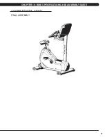
Страница 64: ...61 FINAL ASSEMBLY 10 2 ASSEMBLY INSTRUCTIONS CONTINUED CHAPTER 10 BIKE SPECIFICATIONS AND ASSEMBLY GUIDE...
Страница 73: ...70 NOTES...