


68
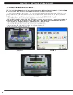
CHAPTER 11: SOFTWARE UPGRADE GUIDE
NOTE: If you install the software while in a self powered mode, keep pedaling while the software is being installed. After the software
has completely loaded, stop pedaling for 30 seconds to allow the machine to completely power down.
1. Create an access on USB folders which will be used. The access should be MATRIX\FW\UCB (create a folder called MATRIX, then a folder
in MATRIX called FW, then a folder in FW called UCB). Or you can put USB in console and follow the steps then the USB will get the access
(Figure A).
2. Copy the software files into the UCB folder on the USB drive (the access should read \MATRIX\FW\UCB - Figure B).
3. Insert the USB drive into the USB port on the console (Figure C).
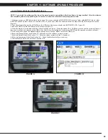
4. When the display is in standard condition, follow the steps as Figure A. Press the speed UP or DOWN keys to choose the correct software (if
there are more than one versions on the USB drive). Once the correct software is found, press ENTER and the upgrade procedure will start.
5. If the console beeps and the standard display picture comes back up, please remove the USB drive.
6. Enter into Manager Mode (see Section 5.1) and make sure the software version is correct.
7. Enter into Service Mode (See Section 7.1). Enter the values recorded in Step 3 (if needed).
8. Enter into Engineering Mode (See Section 6.1). Check that the Machine Type is correct.
9. Test the Bike for function as outlined in Section 9.20.
11.1 SOFTWARE UPGRADE PROCEDURE FOR CONSOLE
FIGURE B
FIGURE A
FIGURE C
Содержание U3X-05
Страница 1: ...U 3 X 0 5 B I K E S E R V I C E M A N U A L...
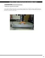
Страница 4: ...1 1 1 SERIAL NUMBER LOCATION CHAPTER 1 SERIAL NUMBER LOCATION FRAME SERIAL NUMBER LOCATION...
Страница 15: ...12 8 1 ELECTRICAL DIAGRAMS CHAPTER 8 TROUBLESHOOTING...
Страница 16: ...13 8 1 ELECTRICAL DIAGRAM CHAPTER 8 TROUBLESHOOTING...
Страница 17: ...14 8 1 ELECTRICAL DIAGRAMS CONTINUED CHAPTER 8 TROUBLESHOOTING MCB POWER WIRE DIGITAL COMMUNICATION WIRE...
Страница 18: ...15 PULSE SENSOR WIRE RIGHT CHAPTER 8 TROUBLESHOOTING 8 1 ELECTRICAL DIAGRAMS CONTINUED PULSE SENSOR WIRE LEFT...
Страница 19: ...16 8 1 ELECTRICAL DIAGRAMS CONTINUED CHAPTER 8 TROUBLESHOOTING PULSE EXTENDED WIRE...
Страница 20: ...17 8 2 LCB LED INDICATORS CHAPTER 8 TROUBLESHOOTING...
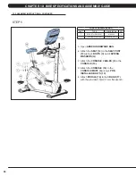
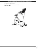
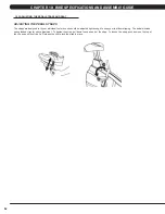
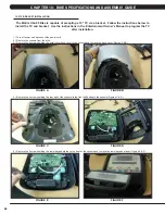
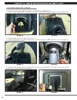
Страница 64: ...61 FINAL ASSEMBLY 10 2 ASSEMBLY INSTRUCTIONS CONTINUED CHAPTER 10 BIKE SPECIFICATIONS AND ASSEMBLY GUIDE...
Страница 73: ...70 NOTES...


