background image

11

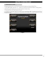
4.8 AUTO CALIBRATION INSTRUCTIONS

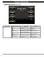
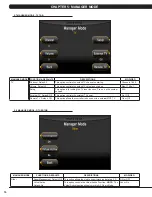
CHAPTER 4: CONSOLE OVERLAY AND WORKOUT DESCRIPTION

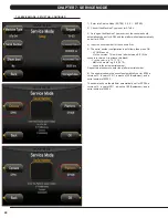
AUTO CALIBRATION PROCEDURE

After initial installation or replacement of the incline motor, auto calibration should be run.  

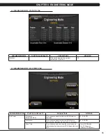
1)  Press ENTER, 2, 0, 0, 1, ENTER on the keypad to go into Engineering Mode.  

2)  Press the key next to CALIBRATION on the display.  

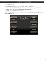
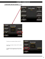
3)  Press the key next to AUTO CALIBRATION on the display.  

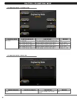
4)  Press the key next to START on the display.  

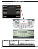
5)  This will run the Auto Calibration.  If the calibration passes, it will say complete.  Press and hold the STOP key to return to the normal start 

screen.  

6)  If the calibration does not pass, contact Matrix Customer Technical Support at 866-693-4863 ext 3.  

Содержание A7X-04

Страница 1: ...A 7 X 0 4 S I N G L E I N C L I N E M O T O R A S C E N T T R A I N E R S E R V I C E M A N U A L...

Страница 2: ...Mode Time Tab 13 5 4 Manager Mode Defaults Tab 14 5 5 Manager Mode Language Tab 15 5 6 Manager Mode TV Tab 16 5 7 Manager Mode Other Tab 16 CHAPTER 6 ENGINEERING MODE 6 1 Engineering Mode Overview 17...

Страница 3: ...t 55 9 13 Incline Motor Replacement 56 9 14 Dual Action Handlebar Replacement 59 9 15 Foot Pedals Replacement 60 9 16 Pedal Arm Replacement 61 9 17 Link Arm Replacement 62 9 18 Swing Arm Replacement 6...

Страница 4: ...1 SERIAL NUMBER LOCATION CHAPTER 1 SERIAL NUMBER LOCATION 1 1 SERIAL NUMBER LOCATION...

Страница 5: ...2 1 1 SERIAL NUMBER LOCATION CONTINUED UNIVERSAL CONSOLE SERIAL NUMBER LOCATION CONSOLE SERIAL NUMBER LOCATION CHAPTER 1 SERIAL NUMBER LOCATION...

Страница 6: ...this unit by it s supply cord or use the cord as a handle Close supervision is necessary when the Ascent Trainer is used by or near children or disable persons Do not use outdoors Do not operate where...

Страница 7: ...d circuit GROUNDING INSTRUCTIONS The Matrix Ascent Trainer must be grounded If it should malfunction or break down grounding provides a path of least resistance for electric current to reduce the risk...

Страница 8: ...ipment free from dust and dirt DO NOT use any equipment that is damaged or has worn or broken parts Use only replacement parts supplied by Matrix Fitness Systems MAINTAIN LABELS AND NAMEPLATES Do not...

Страница 9: ...ipment each time service or maintenance is performed You may periodically see addendums to this document as the Matrix Technical Support Team identifies items that require specific attention the lates...

Страница 10: ...FAN Allows for fan speed selection fan has 3 operating speeds 4 1 CONSOLE DESCRIPTION A7X ENTERTAINMENT ZONE IPOD Will take the user directly to the iPod screen to allow for iPod control and play list...

Страница 11: ...pts to set 4 Select the key next to Weight and follow the prompts to set 5 Select the key next to GO and the display will read 3 2 1 and then the program will begin GLUTE TRAINING WORKOUT This program...

Страница 12: ...st ends a recovery period cool down will begin and the user s results are calculated and displayed Results are based on the number of stages completed Incline will not be adjustable during the test 1...

Страница 13: ...xt to TARGET HEART RATE 2 Select the key next to Age and follow the prompts to set 2 Select the key next to Percent of HR and follow the prompts to set 3 Select the key next to Time and follow the pro...

Страница 14: ...the keypad to go into Engineering Mode 2 Press the key next to CALIBRATION on the display 3 Press the key next to AUTO CALIBRATION on the display 4 Press the key next to START on the display 5 This wi...

Страница 15: ...normal operation NOTE If a setting has been changed the unit and console power should be reset Cycle the power switch and press and hold the CHANNEL UP and CHANNEL DOWN keys for 3 5 seconds to reset t...

Страница 16: ...he club to set the maximum workout duration limits during peak and non peak hours Maximum 99 Minutes Minimum 5 Minutes Pause Time Default 5 Minutes This option controls the default pause time Maximum...

Страница 17: ...150 lbs 68 kg This option controls the default weight used in the calorie calculations Displayed in pounds or kilograms Maximum 400 lbs 182 kg Minimum 50 lbs 22 kg Height Default 68 or 173cm This opti...

Страница 18: ...elect default language This option allows the user to select a flag for a specific language N A FLAG UNIT Mile Mile KM KM KM LANGUAGE English German FLAG UNIT KM KM KM KM KM LANGUAGE Spanish Dutch Ita...

Страница 19: ...controls the external TV power On Off Remote TV Default Off This option allows the controller to be used with a external MYE TV On or Off MANAGER MODE TV 5 7 MANAGER MODE TV TAB 5 8 MANAGER MODE OTHE...

Страница 20: ...Select the key next to the setting that needs to be changed and follow the prompts to change 3 Press the ENTER key once the desired setting is correct to save 4 Press HOME or press and hold the STOP...

Страница 21: ...ne for incline motor 1 Bottom 0 1 25 5 Tune Incline 2 Top Top 2 0 Sets the maximum incline for incline motor 2 Top 0 1 25 5 Tune Incline 2 Bottom Bottom 2 0 Set the minimum incline for incline motor 2...

Страница 22: ...is option controls the minimum RPM limits for operation 25 99 RPM Disconnect This option controls the minimum RPM limit to operate other functions when no power is present 20 60 RPM Keep Time This opt...

Страница 23: ...is option allows the club to select a screen header from a list N A 6 6 ENGINEERING MODE CLUBS TAB ENGINEERING MODE FUNCTION DEFAULTS DESCRIPTIONS MODIFIED Club ID This option records the Club ID of t...

Страница 24: ...at needs to be changed and follow the prompts to change 3 Press the ENTER key once the desired setting is correct to save 4 Press HOME or press and hold the STOP key for 3 5 seconds to return to norma...

Страница 25: ...ccumulated Distance This option displays the accumulated workout distance since production Accumulated Time This option displays the accumulated workout time since production Show Boot Factory Setting...

Страница 26: ...his setting is for self powered frames A5x 03 F with dual incline motors This setting is for the new suspension style Ascent Trainer A5x 04 F This is the setting that should be used for this model 7 2...

Страница 27: ...ion is as follows then press OK V YY MM nnnnn V is the version This will be a letter between B Z if the console is version A just leave this blank Y is the year e g 10 11 12 MM is the month e g 08 09...

Страница 28: ...ESCRIPTIONS Keypad This option is for a keypad test Auto Calibration This option auto calibrates the lift motor Radio Test This option is for a radio test SERVICE MODE Test 7 3 SERVICE MODE TEST TAB C...

Страница 29: ...26 SERVICE MODE FUNCTION DEFAULTS DESCRIPTIONS Time Date Time This option sets the current date and time on the machine 7 4 SERVICE MODE DATE TIME TAB CHAPTER 7 SERVICE MODE...

Страница 30: ...ICE MODE LOG TAB FUNCTION DEFAULTS DESCRIPTIONS Delete This option deletes key components replacement history Create This option creates key components replacement history SERVICE MODE Log CHAPTER 7 S...

Страница 31: ...28 8 1 ELECTRICAL DIAGRAMS CHAPTER 8 TROUBLESHOOTING...

Страница 32: ...29 8 1 ELECTRICAL DIAGRAMS CONTINUED CHAPTER 8 TROUBLESHOOTING P21 Digital Communication Wire...

Страница 33: ...30 8 1 ELECTRICAL DIAGRAMS CONTINUED CHAPTER 8 TROUBLESHOOTING P25 Hand Pulse Connecting Cable...

Страница 34: ...Incline 2 Rearward LED 12 Charge LED 13 Discharge LED 14 12V 6A main power LED 15 Console Power LED 16 E_RPM external LED 17 15V 8A charge power LED 18 Cool Fan CHAPTER 8 TROUBLESHOOTING LED PULSES S...

Страница 35: ...ce the LCB 0X01AF The power resistor is disconnected Check the connection of the resistor at the LCB Replace the LCB if needed 0x01B2 The incline motor has no action or current Replace the incline mot...

Страница 36: ...able d If plugging the coax cable into the back of the console does not resolve the issue remove the console back and check the console cable connection at the tuner Figure C e Check the internal cabl...

Страница 37: ...LCB LEDs If the incline LED is not a solid light only one LED will show a solid light at a time replace the LCB Figure A b If the LCB incline LEDs are solid use a multi meter to check the fuses They...

Страница 38: ...ation Measure the incline VR value Figure A by measuring across the Blue Orange and Brown Orange wiring in the incline motor wire harness The VR range should be 0 5k 9 5k ohms for example if the circu...

Страница 39: ...LED 15 is not lit check for incoming AC voltage at the LCB Replace the power components as needed if the voltage is not present Replace the LCB if all power components are ok and there is AC voltage t...

Страница 40: ...at nothing is touching the heart rate grips For example the safety key string or headphone wiring There are some things that will interfere with heart rate signal These include florescent lighting ele...

Страница 41: ...B 2 Remove the 3 screws holding the disk to the axle Figure C 3 Remove the disk Figure D 4 Reverse Steps 1 3 to install a new disk NOTE There is a tab on the disk that should be lined up with a slot o...

Страница 42: ...cure the handlebar so that it is out of the way Figure D 4 Remove the front disks as outlined in Section 9 1 5 Detach the pedal arm from the crank bearing assembly Figure E 6 Remove the 2 screws that...

Страница 43: ...older plastic and remove it from the unit Figure H 9 Remove the 2 screws to disassemble and remove the middle stabilizer sweat cover Figures I J 10 Remove the 1 screw exposed when the cup holder is re...

Страница 44: ...nt shrouds from the frame or each other Figure M 13 Turn the crank to the slotted portion of the shroud Figure N 14 Remove the front shrouds for frame access Figures O P 15 Reverse Steps 1 14 to insta...

Страница 45: ...ont disks from the machine as outlined in Section 9 1 3 Disconnect all wires from the LCB Figure A 4 Remove the 2 screws holding the LCB to the frame Figure B 6 Reverse Steps 1 4 to install a new LCB...

Страница 46: ...ront shrouds as outlined in Section 9 2 4 Cut the cable tie holding the cable to the frame Figure A 5 Unplug the power cable connector of the generator Figure B 6 Loosen the nut holding the generator...

Страница 47: ...erator belt Figure F 10 Remove the generator from the frame 11 Reverse Steps 1 10 to install a new generator Re install the belts as outlined in Section 9 5 NOTE The 3 screws removed in Step 7 should...

Страница 48: ...tlined in Section 9 4 5 To install a new belt first put the belt installation tool on the pulley Figure A 6 Put the new belt on the installation tool Figure B 7 Turn the pulley until the belt is insta...

Страница 49: ...e the pulley counter clockwise until there is enough slack in the belt to remove it Figures A B 4 Install the replacement belt and reverse necessary steps to secure the assembly until the belt is tigh...

Страница 50: ...rame Figure B 5 On the left side of the frame remove the retaining ring that holds the pulley axle bearing into the frame Figure C 6 Remove the pulley axle set assembly from the frame Clean any debris...

Страница 51: ...f the frame remove the retainer clip that holds the drive axle bearings in the frame Figure A 5 Install an M10 screw into the drive axle Figure B 6 Turn the screw until the head is close to the drive...

Страница 52: ...into the left side of the frame Figure I 13 Mount the other tool from Figure H behind the bearing cap portion of the tool Use the M10 x 65L screw with a washer and a nut to attach the tool to the driv...

Страница 53: ...asher and a nut to attach the tool to the drive axle Figure O 19 Turn the screw at least 4 full revolutions into the drive axle Then turn the nut until it is close to the cup portion of the tool Figur...

Страница 54: ...CHAPTER 9 PART REPLACEMENT GUIDE 22 Use a screwdriver to remove the iron plate from the drive axle Figures S T 23 Re install the belts as outlined in Sections 9 5 and 9 6 24 Test the Ascent Trainer as...

Страница 55: ...ank Figure A 4 Insert an M10 screw should be at least 40 long into the crank hole Then turn the screw until the crank can be separated from the axle Figure B 5 Install the replacement crank There shou...

Страница 56: ...e 5 screws that hold the mounting plate to the console Figure C 5 Attach the mounting plate to the new console 6 Connect the wire connections to the new console 7 Carefully push the wires into the con...

Страница 57: ...onsole area with alcohol to remove any left over adhesive Figure C 5 Peel part of the protective film from the back of the overlay keypad Figure D 6 Push the overlay keypad ribbon cable through the ho...

Страница 58: ...the protective film Figures G H 8 Once the overlay keypad is in the correct position press down on it to adhere it in positions Figure I 9 Use the same procedure to replace any additional faulty over...

Страница 59: ...arefully remove the wires from inside the console mast until the connectors on the ends come free and disconnect Figure C 6 To install a new handlebar assembly connect the new handlebar and carefully...

Страница 60: ...nd disconnect the incline motor power wire Figures A B If unsure if the incline motor is the issue plug in the new incline motor at this time to see if it is energized If it is not the issue is likely...

Страница 61: ...ers should turn smoothly with only a small amount of friction Figure E 8 If the rollers need to be adjusted loosen the horizontal bolts simultaneously first then adjust the roller friction by adjustin...

Страница 62: ...ween the carriage and the frame Use an 8mm Allen wrench to maintain this spacing Figure H NOTE Figure H shows a unit with the console mast removed for clarity 13 Turn the nut on the incline motor unti...

Страница 63: ...two bolts that hold on the pivot cap and remove the cap Figure C 4 Unplug and separate the heart rate connector exposed once the pivot cap is removed Then remove the 4 screws that hold the dual actio...

Страница 64: ...ews that hold the plastic pedal to the foot plate Figure B 3 Remove the plastic foot pedal Figure C 4 Clean the foot plate to remove any rubber or debris 5 Reverse Steps 1 4 to install a new foot peda...

Страница 65: ...gether Figure D 5 The swing arm can now be separate from the pedal arm Figure E 6 Remove the bolt that holds the link arm to the pedal arm and remove the pedal arm Figure F 7 Reverse Steps 1 5 to inst...

Страница 66: ...d bushings where the dual action handlebar meets the link arm Figure B 3 Remove the bolt that holds the link arm to the pedal arm and remove the link arm Figure C 4 Reverse Steps 1 3 to install a new...

Страница 67: ...and turn it into the shaft Figure D 5 Use a mallet to hit the head of the bolt until the swing arm can be separate from the pedal arm and remove the pedal arm Figures E F 6 Reverse Steps 1 5 to instal...

Страница 68: ...upper pivot joint of the vertical stabilizer arm Figure C 3 Remove the vertical stabilizer arm Figure D 4 Reverse Steps 1 3 to install a vertical stabilizer arm NOTE Tighten the bolt removed in Step 2...

Страница 69: ...LACEMENT CHAPTER 9 PART REPLACEMENT GUIDE 1 Remove the screw that holds the plastic cover on the arm Figures A B 2 Remove the incline arm cover Figure C 3 Reverse Steps 1 2 to install a new incline ar...

Страница 70: ...d using a Phillips screwdriver from the underside of the bar 2 Once the screws are removed lift the part carefully then disconnect any wire connections to fully remove the part This includes any resis...

Страница 71: ...d unit power must be reset for some changes to go into affect Cycle the power switch and press and hold the CHANNEL UP and CHANNEL DOWN keys for 3 5 seconds to reset the console power 3 Without hittin...

Страница 72: ...Display Yes English German French Italian Spanish Dutch Portuguese Chinese Japanese Korean Swedish Finnish Russian Arabic Resistance Levels 25 Workouts Manual Rolling Intervals Fat Burn Glute Training...

Страница 73: ...10 9 GRADE MINIMUM GREEN 5 SCREW M5 X 0 8P X 10L YELLOW 2 SCREW M5 X 0 8 X 12L BLACK 2 BAGS 4 SPRING WASHER 8 2 X 15 4 X 2 0T BLACK 2 BAGS 4 SOCKET HEAD CAP SCREW M8 X 1 25P X 20L 10 9 GRADE MINIMUM...

Страница 74: ...71 10 3 ASCENT TRAINER ASSEMBLY STEPS STEP 1 CHAPTER 10 ASCENT TRAINER SPECIFICATIONS AND ASSEMBLY GUIDE...

Страница 75: ...72 STEP 2 RED HARDWARE BAG 10 3 ASCENT TRAINER ASSEMBLY STEPS CONTINUED CHAPTER 10 ASCENT TRAINER SPECIFICATIONS AND ASSEMBLY GUIDE...

Страница 76: ...73 STEP 3 PINK HARDWARE BAG 10 3 ASCENT TRAINER ASSEMBLY STEPS CONTINUED CHAPTER 10 ASCENT TRAINER SPECIFICATIONS AND ASSEMBLY GUIDE...

Страница 77: ...74 10 3 ASCENT TRAINER ASSEMBLY STEPS CONTINUED CHAPTER 10 ASCENT TRAINER SPECIFICATIONS AND ASSEMBLY GUIDE Torque this bolt to 80 N m STEP 4 GREEN YELLOW HARDWARE BAG...

Страница 78: ...75 STEP 5 RED HARDWARE BAG 10 3 ASCENT TRAINER ASSEMBLY STEPS CONTINUED CHAPTER 10 ASCENT TRAINER SPECIFICATIONS AND ASSEMBLY GUIDE...

Страница 79: ...76 10 3 ASCENT TRAINER ASSEMBLY STEPS CONTINUED CHAPTER 10 ASCENT TRAINER SPECIFICATIONS AND ASSEMBLY GUIDE STEP 6...

Страница 80: ...77 10 3 ASCENT TRAINER ASSEMBLY STEPS CONTINUED CHAPTER 10 ASCENT TRAINER SPECIFICATIONS AND ASSEMBLY GUIDE STEP 7 BLUE BLACK HARDWARE BAG...

Страница 81: ...78 10 3 ASCENT TRAINER ASSEMBLY STEPS CONTINUED CHAPTER 10 ASCENT TRAINER SPECIFICATIONS AND ASSEMBLY GUIDE STEP 8 WHITE HARDWARE BAG...

Страница 82: ...79 10 3 ASCENT TRAINER ASSEMBLY STEPS CONTINUED CHAPTER 10 ASCENT TRAINER SPECIFICATIONS AND ASSEMBLY GUIDE STEP 9 PINK HARDWARE BAG...

Страница 83: ...80 10 3 ASCENT TRAINER ASSEMBLY STEPS CONTINUED CHAPTER 10 ASCENT TRAINER SPECIFICATIONS AND ASSEMBLY GUIDE STEP 10 PINK HARDWARE BAG...

Страница 84: ...81 10 3 ASCENT TRAINER ASSEMBLY STEPS CONTINUED CHAPTER 10 ASCENT TRAINER SPECIFICATIONS AND ASSEMBLY GUIDE STEP 11 PINK HARDWARE BAG...

Страница 85: ...82 10 3 ASCENT TRAINER ASSEMBLY STEPS CONTINUED CHAPTER 10 ASCENT TRAINER SPECIFICATIONS AND ASSEMBLY GUIDE STEP 12 PINK HARDWARE BAG...

Страница 86: ...for optimum use Once you have placed your unit where you intend to use it raise or lower one or both of the adjustable levelers located on the bottom of the frame Use a 6mm Allen wrench through the ac...

Страница 87: ...the number keypad and a Menu will appear on the TV Figure C NOTE Once the Menu is present on the screen the following buttons must be pressed quickly or the Menu will minimize after 5 seconds of no ke...

Страница 88: ...gh signal to come in clearly or will fail to pick up channels that do come in clearly Use the following procedure to manually add or delete a channel 1 Follow Steps 1 4 in the Auto Scan instructions t...

Страница 89: ...d a Menu will appear on the TV Figure M 5 Use the VOLUME UP or DOWN keys to scroll the cursor to Setup on the Menu Figure N 6 Use the CHANNEL UP or DOWN keys to scroll the cursor to Closed Caption the...

Страница 90: ...n on the standard display picture turns red prior to updating the software 1 Copy five software files SirF7xAll cab NK IO_XXX updateLMM cofige and Extract_CE onto a USB drive 2 Turn on the power to th...

Страница 91: ...T Figure F 7 Press the key next to VERSIONS to verify the new software version Figure G 8 All of the software versions will now be displayed Figure H Press the HOME key to return to the standard displ...

Страница 92: ...89 NOTES...

Страница 93: ...90 MATRIX FITNESS SYSTEMS CORP 1610 LANDMARK DRIVE COTTAGE GROVE WI 53527 USA TOLL FREE 866 693 4863 www matrixfitness com FAX 608 839 1717 REV 1 KO...

Отзывы: