6
In pressure pump mode some of the optional features are disabled, including maximum run alternation, anti-seize
and maximum idle timers
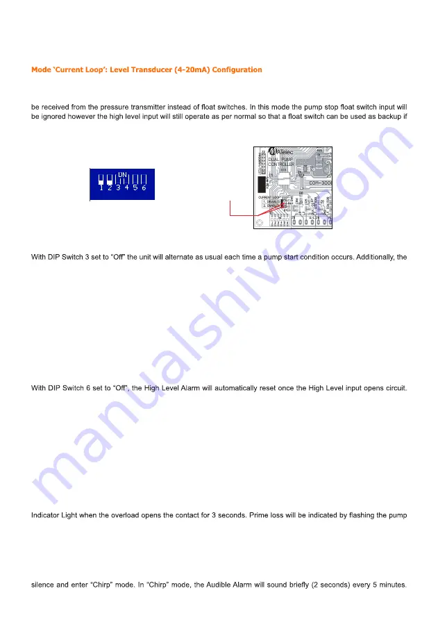
In order to activate current loop mode the enclosure must be opened and jumper J10 moved to the “current loop
enabled” position (as shown in the following picture). By selecting current loop input mode the pump start input can
be connected to a 4-20mA loop powered pressure transducer. The pump start, stop and high level signals can then
desired. The start, stop and high level current set points will be pre-programmed into the software and therefore cannot
be adjusted. The levels for a 0-4m transducer are Stop= 300mm, Start= 600mm and High= 1000mm.
Maximum Run and Alternation Mode
controller will automatically alternate pump duty if a pump has been running continuously for 30 minutes (maximum
run timer) Setting this DIP Switch to “On” will cause the controller to operate in “Circulation Mode” where duty will only
alternate once the pump has run for 6 hours of accumulated time.
Anti-Seize Timer
With DIP Switch 4 set to “On”, the Anti-seize timer will automatically run the pumps for 6 seconds, every 7 days. This
pump operation will completely override all inputs including the low level (if enabled). This feature will only run pumps
that are set in Auto. This “Pump Run”, will alternate between Pump 1 and Pump 2. A pump that has been-locked out
due to a fault will not run.
Manual Mode Timeout
With DIP Switch 5 set to “On” the pump will only remain in Manual Mode for 5 minutes, after which time, it automatically
reverts to Auto.
High Level Alarm Reset
The controller will also use the alternate High Level Alarm Delay. Typically used for Storm Water applications. High
Level Alarm delay in this mode is 15 minutes. Setting this DIP Switch to “On”, will cause the High level Alarm to
remain active until the controller is reset. The High Level Alarm will use the standard High Level Alarm activation delay.
Typically used for Sewerage applications. High Level Alarm delay in this mode is 5 minutes.
Audible and Visual Alarm Test
By pressing the
Mute/Reset
button on the Keypad continuously for a period of 5 seconds, the Strobe, Siren and
indicator Lights will be powered up for inspection.
Fault Reset
To reset all faults on the controller, press and old the Mute/Reset button on the Keypad continuously for a period of 3
seconds until an acknowledgment beep is heard.
Pump Fault
A Pump Fault is indicated for two types of faults. A Thermal Overload will be indicated by way of a steady Fault
fault light slowly.
Level Alarms
A High Level Alarm is indicated by way of a steady Level Alarm Indicator Light.
A Low Level/Low pressure Alarm is indicated by way of a Flashing Level Alarm Light.
Auto Silencing Alarm Feature
The audible Alarm is programmed to sound for 5 minutes continuously, unless muted and will thereafter automatically
Figure 1: APC6 PCB Layout and Current Loop Jumper
Current Loop
Enable Jumper
Dip Switch Setting
Ensure dip switch 1 and 2 are down
in mode A for transducer operation
Содержание FPC-30020-CON
Страница 10: ...10 CIRCUIT DIAGRAM...
Страница 11: ...11 NOTES...


