EN
28
Adjusting the taps:
open the gas flow with the knob and light the bur
-
–
ner to be adjusted,
set the knob in simmering flame position
–
, and
then, maintaining that position, remove the knob
from the tap pin and watch the burner’s flame
turn the adjustment screw “A” (7.4.1) and watch
–
the flame; set the flame to such a size that will pre
-
vent it from being extinguished by a slight draught
or during the operation of quickly turning the knob
from the full to the simmering position of the flame
and back;
the adjustment is correct when the core of the fla
-
–
me is cone-shaped in green and blue colour and is
ca. 2 – 4 mm tall
if there are perceptible changes of gas pressure in
–
the gas supply system (change in the size of fla
-
me at full flow), the simmering flame should be set
when pressure in the system is low to prevent the
burner from extinguishing during normal use,
upon adjusting the taps, put the knob back in its
–
position and turn off the flame.
The amount of gas used with taps set to minimal gas
flow corresponds to ca. 25 % of use when the taps
are set to full flame.
8.1 The cooker is equipped with the power cord with
a plug and must be connected to a mains socket
properly fitted with earth contact (fig. 8.1.1).
8.2 If the power cord is not fitted with a plug, the plug
must be connected to it. The cord must be fitted
with a plug with a proper grounding prong. Befo
-
re connecting to a power supply, ensure that:
– the voltage indicated on the nameplate matches
the mains voltage at the site where the appliance
is connected
– the performance of the power supply at the place
of connection is sufficient to meet the maximum
power requirements of the appliance, as specified
on the nameplate.
The mains socket should be easily accessible
•
to the user.
Make sure that the power cord does not come
•
into contact with hot parts of the cooker.
9.1 Knobs
The gas flow in particular burners is opened and clo
-
sed with the use of knobs fitted on the gas taps. Be
-
fore turning the burner on, make sure that the knob
you are about to turn corresponds to the burner which
is to be used. The burners and their corresponding
knobs are shown in fig. 9.1.1.
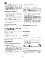
9.2 Setting the flame
The flame should not lick around from the bottom of
a pan. The size of flame depends on the position of
the knob (9.2.1, 9.2.2, 9.2.3).
0 – burner switched off (flow of gas shut off);
- large flame; - small flame (simmering)
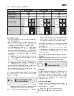
2E-G20 20mbar
2E-G20 13mbar
3B/P-G30 30mbar
Small
burner
X072
084
050
Medium burner
Z097
110
065
Large burner
Y118
145
085
Oven burner
P1
P9
P2
Oven
Arrangement of
burner nozzles
Table 1 Burner nozzle specification
Содержание KG-1514ZSB DYN
Страница 1: ...PL RU EN INSTRUKCJA MONTA U I U YTKOWANIA INSTRUCTION MANUAL KG 1514ZSB DYN O...
Страница 2: ...1 2 6 1 6 4 1 6 6 1 6 6 2 7 4 1 1 1 1 8 1 1...
Страница 4: ...3 10 7 1 10 8 1 10 7 2 10 8 2 11 2 1 11 3 4 11 3 1 11 3 2 11 3 3...
Страница 16: ...RU 15 9 10 11 12...
Страница 17: ...RU 16 6 1 6 2 6 3 6 4 6 5 6 6 650 6 4 1 6 7 6 8 6 6 1 6 6 2 G1 2 7 1 2 0 7 2 0 5 1 5...
Страница 19: ...RU 18 25 8 1 8 1 1 8 2 1 3 10 1 9 1 1 10 2 9 2 1 9 2 2 9 2 3 0 9 2 2 9 2 3 9 2 4 10 3 9 3 1 o 5 1 10 4 0...
Страница 22: ...RU 21 12 1 12 3 11 2 1 1 4 2 5 3 6 12 4 11 3 1 1 2 3 11 3 2...
Страница 23: ...RU 22 45 11 3 3 1 2 13 1 1 13 1 2 13 1 1 13 1 2...
Страница 24: ...RU 23 1 2 1 2 3 E14 230 25 3000C...
Страница 25: ...RU 24 2002 96...
Страница 35: ...EN 34...

