www.masterproducts.es
24
2.
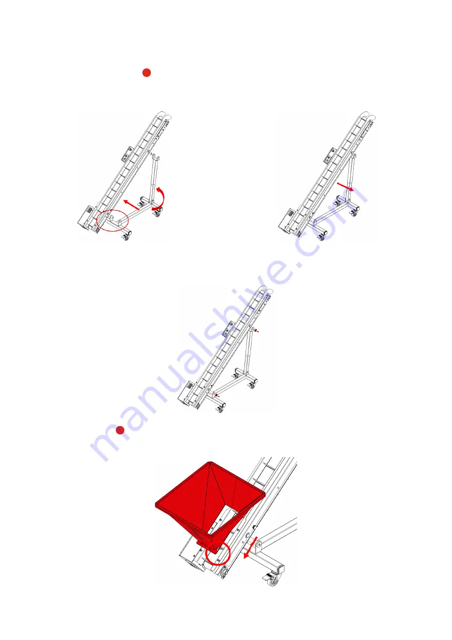
With the help of another person, tilt and hold the conveyor belt until it reaches the position shown in the fo
-
llowing image, approximately. Subsequently, also tilt the telescopic arm and loosen the handle on it so that the tube
can be slid to the desired length. Tighten the handle to fix its position.
Then move the conveyor belt
A
slightly until the upper support shaft can be inserted through the holes in the
U-shaped support at the upper end of the telescopic arm. Make sure that the lower shaft does not come out of the
lower support in order to avoid damage to the equipment and/or the operators.
3.
Once the two shafts have been inserted into the holes of the supports and ensure that the conveyor belt is su
-
pported, fit the two stop washers and screw in the two DIN 7380 M8 screws using an Allen key No. 5.
4.
Fit the feed hopper
C
as shown in the following image. The base of the hopper has four bowler-shaped slots
that allow mounting or dismounting on the equipment without the use of tools.
Содержание Lift Conveyor
Страница 2: ......
Страница 18: ...www masterproducts es 18...
Страница 35: ......
Страница 36: ......


