background image

1

PT

ÍNDICE

1. APRESENTAÇAO DOS PRODUTOS

1. INFORMAÇÕES SOBRE A SEGURANÇA

2. FUNCIONAMENTO

2. PARADA

2. DISPOSITIVOS DE SEGURANÇA

2. TRANSPORTE E MOVIMENTAÇÃO

2. PROGRAMA DE MANUTENÇÃO PREVENTIVA

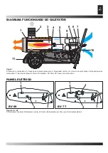
3. DIAGRAMA FUNCIONANDO DO CALEFATOR

3. PAINEL ELÉTRICO

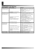
4. INDIVIDUAÇÃO DOS DEFEITOS

APRESENTAÇAO DOS PRODUTOS

Compreende  gerador  de  ar  quente    aquecedor  indireto  que, 

através  um  trocador  de  calor  consente  de  separar  gases  de 

combustao do ar quente no ambiente. Nesse modo, é possivel 

introduzir uma corrente de ar quente e limpa, ao interno do local 

da aquecer e encaminhar ao externo o vapor de descarga.

Projectadas segundo os mais modernos critérios de seguranças, 

funcionalidade e durabilidade:dispositivos de segurança garante 

sempre  um  correcto  funcionamento  da  maquina.  O  impacto 

acustico foi reduzido ao minimo e com uma cuidadosa escolha 

dos materiais garantindo assim uma elevada confiança.

INFORMAÇÕES SOBRE A 

SEGURANÇA

CUIDADOS

IMPORTANTE:ler atentamente e completamente o manual 

de  instruções  antes  de  montar,  acender  ou  fazer  a  ma-

nutenção deste aquecedor. O uso do aparelho pode cau-

sarlesões graves ou fatais como queimaduras, incêndio, 

explosões,  descargas  elétricas  ou  asfixia  causada  por 

monóxido de carbono.

!  PERIGO:A  asfixia  causada  por  monóxido  de  carbono 

pode ser fatal!

Asfixia  causada  por  monóxido  de  carbono  Os  primeiros 

sintomas  da  asfixia  causada  por  monóxido  de  carbono  são 

semelhantes  aos  sintomas  da  gripe,  com  dores  de  cabeça, 

tonturas e/ou náusea.

Tais  sintomas poderiam ser causados pelo mal funcionamento 

do  aquecedor.  Ir  imediatamente  para  um  lugar  ao  ar  livre! 

Consertar  oaquecedor.  Algumas  pessoas  sofrem  mais  os 

efeitos  causados  pelo  monóxido  de  carbono,  especialmente 

as  mulheres  durante  a  gravidez,  ou  aquelas  pessoas  que 

sofrem de doenças cardíacas ou pulmonares, os anêmicos, os 

alcoólatras e todas as pessoas que se encontram em lugares 

de grande altitude. Não esquecer de ler e compreender todas 

as advertências.Conservar este manual para consultas futuras; 

pode ser usado como guia ao funcionamento seguro e correto 

do aquecedor.

•   Usar  somente  óleo  combustível    n°1  para  evitar  os  riscos 

de  incêndio  ou  de  explosão.  Nunca  utilizar  gasolina,  náfta, 

solventes para tintas, álcool ou outros combustíveis altamente 

inflamáveis.

•  Abastecimento: 

a)  O  pessoal  responsável  pelo  abastecimento  deve  ser 

especializado e deve conhecer completamente as instruções do 

fabricante, além de conhecer as normas vigentes relacionadas 

ao abastecimento seguro dos aquecedores.

b)  Usar  somente  o  tipo  de  combustível  expressamente 

especificado sobre a etiqueta de identificação do aquecedor.

c) Antes de efetuar o abastecimento, apagar todas as chamas, 

inclusive a chama piloto, e aguardar que o aquecedor resfrie.

d)  Durante  o  abastecimento,  inspecionar  todas  as  linhas  do 

combustível  e  as  respectivas  conecções,  a  fim  de  encontrar 

eventuais vazamentos. Qualquer tipo de vazamento deve ser 

consertado antes de acionar o aquecedor.

e)  Em  circunstância  alguma  deve-se  conservar  no  mesmo 

edifício,  perto  do  aquecedor,  uma  quantidade  de  combustível 

superior  àquela  necessária  para  manter  o  funcionamento  do 

aquecedor  por  um  dia.  Os  tanques  para  armazenagem  do 

combustível devem ser colocados em uma estrutura separada.

f)  Todos  os  tanques  de  combustível  devem  ser  colocados  a 

uma distância mínima dos aquecedores, do bico de soldas, de 

aparelhos para soldar ou fontes de acendimento similares (com 

exceção do tanque de combustível incorporado ao aquecedor).

g) Sempre que possível, o combustível deve ser conservado em 

locais cuja pavimentação não permita a penetração e o gotejar 

de combustível sobre chamas posicionadas no andar de baixo 

que possam causar o acendimento do mesmo.

h) A conservação do combustível deve ser realizada conforme 

as normas vigentes.

•   Nunca  usar  o  aquecedor  em  locais  em  presença  de 

gasolina,  solventes  para  tintas  ou  outros  vapores  altamente 

inflamáveis.

•  Durante o uso do aquecedor, ater-se a todas as normas locais 

e àsnormas vigentes.

•  Os aquecedores usados próximos a telões, cortinas ou outros 

materiais de cobertura similares devem ser colocados a uma 

distância de segurança. Aconselha-se o uso de materiais de 

cobertura do tipo anti-incêndio.Tais materiais são fixados de 

forma  segura,  evitando  que  se  incendeiem  e  prevenindo  as 

interferências causadas pelo vento com o aquecedor.

•  Usar somente em ambientes privos de vapores inflamáveis ou 

de elevadas concentrações de pó.

•  Alimentar  o  aquecedor  somente  com  corrente  cuja  tensão, 

frequência  e  número  de  fases  sejam  discriminados  sobre  a 

etiquetade identificação.

•   Usar  somente  extensões  com  três  fios  devidamente 

conectados à terra.

•  Colocar o aquecedor quente ou em funcionamento sobre uma 

superfície  estável  ou  nivelada,  de  forma  a  evitar  riscos  de 

incêndio.

•   Quando  o  aquecedor  deve  ser  deslocado  ou  guardado, 

mantê-lo  em  posição  nivelada  para  evitar  o  vazamento  de 

combustível.

•  Manter o aquecedor fora do alcance de crianças e animais.

•  Tirar o aquecedor da tomada quando não estiver sendo usado.

•   Quando  controlado  por  um  termostato,  o  aquecedor  pode 

ligar-se em qualquer momento.

•  Nunca usar o aquecedor em ambientes frequentemente habi-

tados nem em dormitórios.

•  Nunca obstruir a tomada de ar (lado posterior), nem a saída de 

ar (lado anterior) do aquecedor.

•   Quando  o  aquecedor  estiver  quente,  ligado  à  tomada  ou 

em  funcionamento,  o  mesmo  nunca  deve  ser  deslocado, 

manuseado,  abastecido  nem  sujeito  a  qualquer  tipo  de 

manutenção.

Содержание BV 69

Страница 1: ...N vod na obsluhu IT Generatore d aria Calda GB Portable forced air heaters DE Tragbare hochdruck heissluftturbinen ES Calentadores m viles de aire forzado FR Appareils de chauffage individuels air fo...

Страница 2: ...SIFIKASJONER SPECYFIKACJE TEXH ECK E XAPAKTEP CT K TEHNI NI PODATKI TEKNIK VERILER TEHNI KI PODACI MODEL BV 69 BV 77 MAX 20 kW 17 400 kcal h 68 000 Btu h 20 kW 17 400 kcal h 68 000 Btu h 550 m h 550 m...

Страница 3: ...generatore si raffreddi d Nel corso del rifornimento ispezionare tutte le linee del combustibile ed i relativi raccordi alla ricerca di eventuali perdite Qualsiasi perdita va riparata prima di rimette...

Страница 4: ...ensione della spia del pulsante di riarmo 2 Fig 2 Un termostato di sovratemperatura interviene e provoca l interruzione dell alimentazione di gasolio se il generatore si surriscalda il termostato si r...

Страница 5: ...Elettrovalvola combu stibile 7 Pompa 8 Motore 9 Ventola 10 Filtro combustibile 11 Serbatoio Figura 1 1 Interruttore principale 2 Pulsante reset 3 Cavo di alimentazione 4 Presa per termostato ambiente...

Страница 6: ...o verificando la tenuta dei tubi e della guarnizione del filtro 4c Pulire o se necessario cambiare l ugello 5a Controllare il collegamento elettrico ed il termost TS Fig 8 5b Pulire ed eventualmente s...

Страница 7: ...orms concer ning the safe fuelling of the heaters b Only use the type of fuel expressly specified on the identifica tion label of the heater c Before adding fuel extinguish all flames including the pi...

Страница 8: ...ts off the fuel supply if the heater overheats the thermostat resets itself automatically when the temperature in the combustion chamber diminishes and reaches the maximum permitted value Before turni...

Страница 9: ...rcuit 6 Electric fuel valve 7 Fuel pump 8 Motor 9 Fan 10 Filter 11 Fuel tank Figur 1 3 GB 1 Main cable 2 Reset button 3 Power cable 4 Socket for ambient thermostat Figur 2 A B HEATER FUNCTIONING DIAGR...

Страница 10: ...ction between the pump and the motor is intact 4b Check that air has not filtered into the fuel circuit checking the tubes and the filter seal 4c Clean or if necessary replace the nozzle 5a Check the...

Страница 11: ...der Generator abgek hlt ist d Kontrollieren Sie w hrend der Bef llung alle Brennstoffleitungen und die entsprechenden Verbindungen um einen eventuellen lverlust festzustellen Jedes Leck muss reparier...

Страница 12: ...tung der Reset Taste 2 Abb 2 Wenn der Generator berhitzt ist greift ein berhitzungsther mostat ein und bewirkt die Unterbrechung der Brennstoffver sorgung der Thermostat stellt sich selbst zur ck wenn...

Страница 13: ...6 Elektrisches Brennstoffventil 7 lpumpe 8 Motor 9 Ventilator 10 Filter 11 Brennstofftank Abbildung 1 1 Hauptschalter 2 Reset schalter 3 Stromversorgungskabel 4 Steckvorrichtung f r den Raumthermostat...

Страница 14: ...eitung auf Luft berpr fen Schl uche und Filterdichtung berpr fen 4c D se reinigen und wenn n tig ersetzen 5a Stromanschluss berpr fen 5b TS Thermostat berpr fen Fig 8 5c Elektroventil reinigen und wen...

Страница 15: ...s de proveer al abastecimiento apague todas las llamas incluida la piloto y espere que el calentador se enfr e d Durante el abastecimiento inspeccione todas las l neas del combustible y los enlaces co...

Страница 16: ...la luz indicadora del pulsador de reactivaci n 2 Fig 2 Un termostato de sobretemperatura interviene y provo ca la interrupci n de la alimentaci n de gas leo si el generador se recalienta el termostat...

Страница 17: ...tible 6 Electro v lvula combu stible 7 Bomba gas leo 8 Motor 9 Ventilador 10 Filter 11 Tanque combustible Figura 1 1 Interruptor 2 Pulsador reset 3 Cable de alimentaci m 4 Toma por termostato Figura 2...

Страница 18: ...ndo que los tubos y la junta del filtro sean perfectamente estancos 4c Limpie o si necesario cambie la boquilla 5a Controle la conexi n el ctrica 5b Controle el termostato TS Fig 8 5c Limpie y eventua...

Страница 19: ...age soit refroidi d Au cours du ravitaillement inspecter toutes les lignes du combustible et les raccords correspondants afin de v rifier l ab sence de fuites Toute fuite doit tre r par e avant de rem...

Страница 20: ...stat de surtemp rature intervient et provoque la coupu re de l alimentation en gasoil si le g n rateur se surchauffe le thermostat se r arme automatiquement lorsque la temp rature de la chambre de com...

Страница 21: ...ne combustible 7 Pompe gasoil 8 Moteur 9 Ventilateur 10 Filtre 11 R servoir combustible Figure 1 3 FR 1 Interrupteur principal 2 Bouton reset 3 Cordon d alimentation 4 Prise pour thermostat ambiant Fi...

Страница 22: ...ifiant l tanch it des tuyaux et du joint du filtre 4c Nettoyer ou si n cessaire changer la buse 5a Contr ler le branchement lectrique 5b Contr ler le thermostat TS Fig 8 5c Nettoyer et ventuellement r...

Страница 23: ...e brandstof dat specifiek is vermeld op het identificatieplaatje van de verwarmer c Doof voor het bijvullen eerst alle vlammen inclusief de waakvlam en wacht tot de verwarmer is afgekoeld d Inspecteer...

Страница 24: ...een oververhittingsthermostaat geactiveerd die ervoor zorgt dat de olietoevoer wordt onderbroken als de generator oververhit raakt de thermostaat wordt automatisch opnieuw ingesteld zodra de temperat...

Страница 25: ...ktromagnetische brandstofklep 7 Ventilator 8 Motor 9 Oliepomp 10 Filter 11 Brandstoftank Figuur 1 1 Interrupteur principal 2 Reset knop 3 Cordon d alimentation 4 Prise pour thermostat ambiant Figuur 2...

Страница 26: ...uit terecht is gekomen door de afdichting van de leidingen en van de filterbescherming te controleren 4c Reinig of vervang zonodig de straalpijp 5a Controleer de elektrische aansluiting 5b Controleer...

Страница 27: ...c Antes de efetuar o abastecimento apagar todas as chamas inclusive a chama piloto e aguardar que o aquecedor resfrie d Durante o abastecimento inspecionar todas as linhas do combust vel e as respect...

Страница 28: ...amento o aparelho acionar o bloqueio da m quina e oacendimento do led reset 2 Fig 2 Um termostato de superaquecimento se acionar provocando a interrup o da alimenta o do diesel caso o gerador se super...

Страница 29: ...la do combust vel 7 Bomba do diesel 8 Motor 9 Ventilador 10 Filter 11 Tanque do combust vel Figura 1 1 Interrupteur principal 2 Restaurar a tecla 3 Cordon d alimentation 4 Prise pour thermostat ambian...

Страница 30: ...s de ar no circuito do diesel verificando a veda o dos tubos e da guarni o do filtro 4c Limpar ou se necess rio mudar o bico 5a Controlar a conex o el trica 5b Controlar o termostato TS Fig 8 5c Limpa...

Страница 31: ...et og vent at varmeapparatet k ler af d Under p fyldningen kontroll r alle br ndstoflinjerne og de tilh rende tilslutninger for at opspore eventuelle l kager Alle l kager b r repareres f r igangs ttel...

Страница 32: ...dser udstyret maskinen og kontrollampen af genindstillingsknappen 2 Fig 2 t ndes En overtemperatur termostat kobler ind og for rsager afbrydelsen af fyringsolie forsyningen hvis generatoren opheder te...

Страница 33: ...l b 6 Br ndstof elektroven til 7 Forsyningsolie pumpe 8 Motor 9 Bl ser 10 Filter 11 Br ndstof beholder Figur 1 1 Hovedkontakt 2 Reset 3 Tilf rselskabel 4 Stikkontakt for den indvendige temperatur term...

Страница 34: ...ge r rernes t thed og filter pakningen 4c Reng r og udskift dysen hvis n dvendigt 5a Kontroll r den elektriske forbindelse 5b Kontroll r TS termostaten Fig 8 5c Reng r og eventuelt udskift elektroven...

Страница 35: ...ana tarkasta kaikki polttoai nekanavat ja niiden liit nn t ja varmista ettei mik n vuoda Mahdolliset vuodoton ehdottomasti korjattava ennen laitteen k ynnist mist uudelleen e Miss n olosuhteissa ei l...

Страница 36: ...n ja reset merkkivalo syttyy 2 Kuva 2 Generaattorin ylikuumeneminen laukaisee varotermostaatin joka katkaisee polttoaineen sy t n Termostaatti k ynnistyy uudestaan automaattisesti kun palokammion l mp...

Страница 37: ...ava 6 Polttoaineventtiili 7 Polttoainepumppu 8 Moottori 9 Tuuletin 10 Filter 11 Polttoaines ili Kuva 1 3 FI 1 P katkaisija 2 Reset knap 3 Virtajohto 4 Pistoke huoneenl mp termostaatille Kuva 2 A B OHJ...

Страница 38: ...lla letkujen tiiviys ja suodattimen tiiviste 4c Puhdista tai tarvittaessa vaihda polttoainesuutin 5a Tarkista s hk liitokset 5b Tarkista termostaatti TS Kuva 8 5c Puhdista tai tarvittaessa vaihda vent...

Страница 39: ...m vente til anlegget er helt avkj lt d Under fylling av drivstoff m alle forbrenningsr r og utl p kontrolleres for finne eventuelle lekkasjer Enhver lekkasje m repareres f r man setter i gang med bruk...

Страница 40: ...e over oppstartknappen vil sl s p 2 Fig 2 Dersomtermostatenm lerforh ytemperatur vildenf re til attilf rselen av olje vil bli stanset Termostaten vil automatisk f re til gjenoppstart n r temperaturen...

Страница 41: ...ts 6 Elektroventil forbrenning 7 Olje pumpe 8 Motor 9 Vifte 10 Filter 11 Tank forbrenningsolje Figur 1 1 Hovedbryter 2 Reset 3 Elektrisk forsyningskabel 4 Kontakt for romtermostaten Figur 2 A B ELEKTR...

Страница 42: ...retsen ved studere at alle ledninger sitter godt og at pakningene rundt filteret er tette 4c Rense eller bytte oljekran 5a Kontrollere den elektriske tilkoblingen 5b Kontrollere termostaten TS Fig 8 5...

Страница 43: ...aniem uzupe nienia paliwa zgasi wszystkie p omienie wraz z tym g wnym i poczeka a nagrzewnica si och odzi d W celu nape nienia zbiornika sprawdzi ca o obwodu paliwa i odpowiednie po czenia w poszukiwa...

Страница 44: ...j lub wi kszej ilo ci nieprawid owo ci funkcjonowania aparatura ta blokuje maszyn i zapala si wska nik przycisku w czania r cznego 2 Rys 2 Je li generator si przegrzeje termostat wzrostu temperatury p...

Страница 45: ...ektrozaw r paliwa 7 Pompa paliwowa 8 Silnik 9 Wentylator 10 Filter 11 Zbiornik paliwa Rysunek 1 1 G wny wy cznik 2 Przycisk ponownego uruchamiania 3 Kabel zasilania 4 Gniazdo dla termostatu pokojowego...

Страница 46: ...i fotokom rk 4a Skontrolowa ca o po cze pompy i silnika 4b Sprawdzi czy nie nast puje przenikanie powietrza do obwodu paliwa kontroluj c szczelno przewod w i uszczelki filtra 4c Wyczy ci a je eli koni...

Страница 47: ...e a e e e e e e e e e k e e e e e e e o e e e e e e e e e e e e e e e e e e e e e e e e e e e e e e e e e e e e e e e e o e e e e e e e ap c o e e o e e e e e e e c e ae e e e e e e e e e e e e e e e...

Страница 48: ...e 1 e e e 2 e e 2 2 3 e e e e e e O e e e O a e e e 1 2 e e OFF e e e e e e e e e e e e e e e e e e e 2 2 Te e e e e e ep e Te o e e e e e e e e e e e e e e e e e e e e e e e e e e e e e e e e e e e e...

Страница 49: ...3 RU 1 e 2 e po 3 e a 4 5 6 e 7 8 9 e 10 Filter 11 T a 1 1 e e o e e e 2 e 3 p 4 e 2 A B P PA OT 1 2 3 4 5 6 7 8 9 10 11 BV 69 BV 77 1 2 4 3 1 2 3...

Страница 50: ...a o 5 He e e a 1a e e e e 1 e e o e e e 1a e e 1 3 e 2 e 3 e e e 4a e e e e e acoco 4 e e e e e e e 5a e e e e e e e 5 po ep epmoc a TS 8 5 e e e e e o e e e 1 e e e 2 e e 3 e e e 4 e e e 5 e e e e e...

Страница 51: ...lad d B hem dod v n paliva p ekontrolujte v echny cesty paliva a jeho p slu n p pojky aby bylo mo n zabr nit jeho p padn mu niku Jak koli nik mus b t odstran n p ed uveden m topn ho t lesa do chodu e...

Страница 52: ...z stavu stroje a rozsv t se kontrolka tla tka op tovn ho spu t n stroje 2 Obr 2 Dojde k z sahu oteplovac ho termostatu kter vyvol p eru en dod vky motorov nafty pokud se p eh eje gener tor Termostat s...

Страница 53: ...ick ventil paliva 7 Naftov erpadlo 8 otor 9 Ventil tor 10 Filter 11 N dr na palivo Obr zek 1 3 CZ 1 Hlavn sp na 2 Tla itko op tovn ho spu t n 3 Nap jec kabel 4 Z suvka na termostat pro okoln ovzdu Obr...

Страница 54: ...h a to kontrolou t snosti trubek a t sn n filtru 4c Vy istit nebo je li nutn vym nit trysku 5a Zkontrolovat elektrick zapojen 5b Zkontrolovat termostat TS Obr 8 5c Vy istit a p padn vym nit elektrick...

Страница 55: ...yagot t ltene a k sz l kbe minden l ngot oltson el bele rtve a gy jt l ngot is s v rja meg m g a h l gf v kih l d zemanyag felt lt s alatt ellen rizze valamennyi zemanyagvezet ket s a hozz tartoz csat...

Страница 56: ...pcsol a t lmeleged si termoszt t s megszak tja a g zolaj bet pl l st a termoszt t automatikusan visszakapcsol amikor a t zt r h m rs klete a megengedett legmagasabb rt kre cs kken Miel tt ism t zembe...

Страница 57: ...5 zemanyag cirkul ci s k r 6 zemanyag m gnesszelep 7 G zolajszivatty 8 otor 9 Ventil tor 10 Filter 11 zemanyag tart ly bra 1 3 HU 1 F kapcsol 2 jraindit s kapcsol 3 Bet p k bel 4 Termoszt t csatlakoz...

Страница 58: ...lja meg a cs vek s a filter t m t s t 4c Tiszt tsa meg illetve sz ks g eset n cser lje ki a f v k t 5a Ellen rizze a villamos csatlakoz st 5b Ellen rizze a TS termoszt tot bra 8 5c Tiszt tsa meg ille...

Страница 59: ...tero dobro pozna navodila proizvajalca in vse predpise za pravilno tankanje ogrevalnikov b Morate uporabljati samo tisto gorivo katero je navedeno na identifikacijski tablici katera je pritrjena na og...

Страница 60: ...i ge kontrolna lu ka gumba za ponovno vklju itev 2 skica 2 Termostat za pretirano temperaturo se vklju i tako da preneha napajanje dizel goriva e je generator preve vro termostat se samodejno ponovno...

Страница 61: ...oventil za gorivo 6 Vezje za napajanje goriva 7 Loputa 8 Motor 9 rpalka 10 Streme za privijanje kabla 11 Rezervoar 12 Komandna plo a Skica 1 1 Glavno stikalo 2 Kontrolna lu ka za napetost 3 Napajalni...

Страница 62: ...te da ni zraka v vezju za napajanje goriva in dobro kontrolirajte neprepustnost cevi in tesnila filtra 4c O istite ali e je potrebno zamenjajte obo 5a Dobro preverite elektri no povezavo in termostat...

Страница 63: ...ali esnas nda t m yak t hatlar n ve ili kin rakorlar n olas ka ak bulunup bulunmad n kontrol etmek zere tefti ediniz Her t rl ka ak jenerat r tekrar isletmeye al nmadan nce onar lmal d r e Hi bir duru...

Страница 64: ...Bir as r s cakl k termostat m dahalede bulunur ve jenerat r as r s nm s ise mazot beslemesinin kesilmesine sebep olur yanma odas n n s cakl kabul edilen maksimum de ere ulasana kadar d st nde termosta...

Страница 65: ...6 Yak t devresi 7 Fan 8 Motor 9 Pompa 10 Kablo sarma braketi 11 Depo 12 Kumanda panosu Resim 1 3 TR 1 Ana salter 2 Gerilim ikaz lambas 3 Besleme kablosu 4 Ortam termostat prizi ELEKTRIK PANOSU 1 2 3...

Страница 66: ...hava infiltrasyonlar n n olmad n kontrol ediniz 4c Noz l temizleyiniz veya gerekli ise de istiriniz 5a Elektrik ba lant s n ve TS termostat n kontrol ediniz Res 8 5b Elektro vanay temizleyiniz ve gere...

Страница 67: ...c Prije punjenja gorivom potpuno ugasiti stroj i pri ekati da se generator ohladi d U toku punjenja gorivom pregledati sve prolaze goriva i spojke ne bi li se prona li eventualni dijelovi gdje gorivo...

Страница 68: ...u ivanje kontrolnog svjetla gumba za ponovno opremanje 2 Slika 2 Termostat za nadtemperaturu uzrokuje prekid napajanja gorivom ukoliko se generator pregrije termostat se ponovno automatski pokrene kad...

Страница 69: ...il goriva 6 Ciklus goriva 7 Ventilator 8 Motor 9 Pumpa 10 Zahvatnik za namotavanje kabela 11 Spremnik 12 Komandna plo a Slika 1 1 Glavni prekida 2 Kontrolno svjetlo napona 3 Kabel za napajanje 4 Uti n...

Страница 70: ...e filtra ne propu taju 4c O istiti ili ako je potrebno zamijeniti trcaljku 5a Provjeriti elektri nu vezu i termostat TS Slika 8 5b O istiti i eventualno zamijeniti elektri ni ventil Ventilator se pokr...

Страница 71: ...pildami kur u gesinkite visas liepsnas tuo tarpu ir pagrindin liepsn bei palaukite kol ildytuvas atau d Nor dami pripilti kur patikrinkite vis kuro sistem ir atitinkamas jungtis sitikinkite kad nesam...

Страница 72: ...rankinio jungimo mygtuko indikatorius 2 fig 2 ildytuvui perkaitus temperat ros augimo termostatas i jungia kuro tiekim Termostatas automati kai i sijungia degimo kameros temperat rai nukritus iki mak...

Страница 73: ...vas 7 Kuro siurblys 8 Variklis 9 Ventiliatorius 10 Kablys laidui 11 Kuro talpa Fig 1 1 Pagrindinis jungiklis 2 Rankinio jungimo mygtukas 3 Maitinimo laidas 4 Aplinkos termostato lizdas Fig 2 A B 3 LT...

Страница 74: ...itikinkite kad kuro sistem neprasiskverbia oras 4c Pravalykite o jei reikia pakeiskite purk tuv 5a Patikrinkite elektros jungt 5b Patikrinkite TS termostat fig 8 5c Nuvalykite arba pakeiskite elektrin...

Страница 75: ...r skaidri nor d ts sild t ja identifik cijas mar ejum c Pirms iek rtas uzpild anas ar degvielu izdzesiet visas atkl t s liesmas ieskaitot ar indik cijas lampi as un pagaidiet kamer sild t js atdzis s...

Страница 76: ...padevi ja sild t js p rkarst is termostats palai as un izsl dzas autom tiski kad temperat ra deg anas kamer normaliz jas vai sasniedz maksim li pie aujamo l meni Noteikti noskaidrojiet un nov r iet t...

Страница 77: ...tors 9 Ventilators 10 Balstenis kabelim 11 Degvielas tvertne 12 Vad bas panelis Skat 1 1 Galvenais vads 2 przycisk ponownego uruchamiania 3 Baro anas kabelis 4 Kontaktligzda apk rt j s vides temperat...

Страница 78: ...diet vai degvielas kan l nav iefiltr jies gaiss apskatot cauru vadus un filtra izol ciju 4c Izt riet vai ja nepiecie ams nomainiet sprauslu 5a P rbaudiet elektriskos savienojumus 5b P rbaudiet TS term...

Страница 79: ...b Kasutage ainult soojendi identifitseerimistahvlil m rgitud k tuseliiki c Enne paagi t itmist kustutage k ik leegid ja tuled signaallamp kaasa arvatud ning oodake kuni soojendi maha jahtub d Tankide...

Страница 80: ...umenemise korral katkestab lekuumenemistermostaat k tuse pealevoolu termostaat l litub automaatselt v lja kui temperatuur p lemiskambris langeb maksimaalse lubatud v rtuseni Enne soojendi taask ivitam...

Страница 81: ...K tuse solenoidklapp 7 K tusepump 8 Mootor 9 Ventilaator 10 Kaablim hise kandur 11 K tusepaak joonis 1 1 Peal liti 2 Taaskaiviiusnupp 3 Toitekaabel 4 Toatermostaadi pistikupesa TALITLUSSKEEM ELEKTRIL...

Страница 82: ...ei ole sattunud hku vaadates le juhtmed ja filtritihendi 4c Puhastage vajadusel aga vahetage d s v lja 5a Kontrollige elektriliiteid 5b Kontrollige TS termostaati joonis 8 5c Puhastage v i vahetage v...

Страница 83: ...c rile inclusiv flac ra principal i a tepta i p n ce nc lzitorul se r ce te d n vederea umplerii rezervorului verifica i ntregul circuit al combustibilului i racord rile corespunz toare pentru a desc...

Страница 84: ...ndicatorul butonului de cuplare manual 2 fig 2 Dac nc lzitorul se supra nc lze te termostatul temperaturii va determina decuplarea aliment rii cu combustibil Termostatul se va decupla automat dac temp...

Страница 85: ...m bustibil 7 Pompa de combustibil 8 Motor 9 Ventilator 10 C rlig cablu nf urat 11 Rezervor de combustibil Fig 1 1 ntrerup tor principal 2 Buton de cuplare manual 3 Cablul de alimentare electric 4 Priz...

Страница 86: ...iturile filtrului sunt etan e 4c Cur a i i n caz de necesitate nlocui i duza 5a Verifica i contactele electrice 5b Verifica i termostatul TS fig 8 5c Cur a i i eventual schimba i electroventilul Venti...

Страница 87: ...lamene vr tane hlavn ho a po kajte k m sa ohrieva ochlad d Za elom doplnenia paliva skontrolujte v etky palivov pr vody a pr pojky vzh adom na mo nos pretekania Ka d nik paliva mus by odstr nen e te p...

Страница 88: ...ebo nieko ko nepravidelnost prev dzky zablokuje pr stroj a rozsvieti sa kontrolka manu lneho sp ania 2 fig 2 Ak sa gener tor prehreje termostat preru pr sun paliva Termostat sa zapne znova automaticky...

Страница 89: ...k ventil paliva 7 Palivov erpadlo 8 Elektromotor 9 Ventil tor 10 H k pre zv janie k bla 11 Palivov n dr Fig 1 1 Hlavn vyp na 2 Butonul de re pornire 3 K bel elektrick ho pr du 4 Z suvka izbov ho termo...

Страница 90: ...ov ho syst mu v d sledku netesnosti pr vodov a tesnenia filtra 4c Vy istite trysku alebo v pr pade potreby ju vyme te 5a Skontrolujte elektrick spoje 5b Skontrolujte termostat TS fig 8 5c Vy istite al...

Страница 91: ...1 BG 1 1 2 2 2 2 2 3 3 4 O 1 a b c d e f g h...

Страница 92: ...2 BG 3 1 2 ON 1 2 2 1 2 2 2 3 1 2 OFF 2 2 1 6 50 3 4...

Страница 93: ...3 BG 1 2 3 4 5 6 7 8 9 10 11 1 1 2 3 4 1 2 3 4 5 6 7 8 9 10 11 2 A B BV 69 BV 77 1 2 4 3 1 2 3...

Страница 94: ...4 BG 1 2 1a 220 240V 50 Hz 1b 1c 2 1 2 3 4 5 1a 1b 1c 1d 2 3 4a 4b 4c 5a 5b TS 8 5c 1 2 3 4 5 6 1a 1b 1c 2 3a 3b 4 5a 5b 6a 6b 1 1 1 1 TR 8...

Страница 95: ...REGULATION OF COMBUSTION AIR SHUTTER REGELUNG DER VERBRENNUNGSLUFTKLAPPE REGULACI N REGISTRO AIRE PARA LA COMBUSTI N R GLAGE DU RIDEAU AIR COMBURANT AFSTELLING VERBRANDINGSLUCHTKLEP REGULAGEM DA V LVU...

Страница 96: ...LACERING OCH DIMENSIONER SCHEMAT ZAINSTALOWANIA RURY SPALIN CXEMA PAC O O EH MOBO TPY SCH MA UM ST N TRUBEK NA KOU SHEMA POSTAVITVE CEVI ZA DIME DUMAN BORULARINI YERLESTIRME SEMASI 6 1 1 120 mm Fig 7...

Страница 97: ...ermostaten Uttag f r extern term Gniazdo termostatu pokojowego o e e e e e Z suvka termostatu pro okoln ovzdu K rnyezeti leveg termoszt t csatlakoz R Rel Relay Relais Rel Rel Rel Przeka nik Pe e TGR1...

Страница 98: ...GSKIT KIT PARA TUBAGENS SAMLINGSSAET TIL SLANGE LIITT MISSARJA ZESTAW POD CZENIOWY CS CSATLAKOZ K SZLET KIT ZA PRIKLOP CEVI SPOJNICA ZA ELASTI NO CRIJEVO ARN JUNG I KOMPLEKTAS TENES SAVIENOJUMA KOMPLE...

Страница 99: ...9 1 2 3 X1 X4 X4 X2 4 3 2 1 4 ISTRUZIONI MONTAGGIO MANIGLIA HANDLE ASSEMBLY SCH MA DE MONTAGE DE LA POIGN E GRIFFEINBAU ANLEITUNG ISTRUCCI N DE MONTAJE MANIJA...

Страница 100: ...lesa na dm chan vzduch Kilnojami auk to sl gio oro ildytuvai Kaasaskantav husoojendi P rvietojamie gaisa sild t ji ar piespiedu gaisa padevi Priprava za vpihavanje toploga zraka Portat f basin li hava...

Страница 101: ...___________________________________ ____________________________________________________________________________________ _______________________________________________________________________________...

Страница 102: ...e do seu produto velho O seu produto est concebido e fabricado com materiais e componentes da mais alta qualidade os quais podem ser reciclados e reutilizados Quando o s mbolo de um caixote do lixo co...

Страница 103: ...turi b ti atiduota perdirbimui Informacij apie panaudotos elektrin s rangos rinkimo sistem galima gauti rengini pardavimo vietose bei i gamintojo arba importuotojo EE Informatsioon kasutatud elektroo...

Страница 104: ...DESA ITALIA s p a via Tione 12 37010 Pastrengo Verona Italy www desaitalia com info desaitalia com DESA POLAND Sp Z o o ul Magazynowa 5A 62 023 Gadki Poland www desapoland pl office desapoland pl...

Отзывы: