background image


Enter the distances found on the “Measured Distance” fields and hit “Calculate!” 

CORE-1 will 

automatically calculate and apply optimum values for Balance and Time Alignment, so you 
don’t have to worry about doing it manually

. This will result in perfect soundstage, as if all 

speakers were perfectly aligned and at the same distance from the listener. The picture on the left 
shows a typical example of a 3-Way system alignment using Subwoofer, Mid-Bass and Tweeters.


If you wish to perform the Time Alignment manually, just drag the sliders corresponding to the 

delay-distance on the (L) and (R) sides until you get appropriate soundstage imaging. You can also 
type the distance-delay that you wish to achieve by typing inside the fields and then pressing TAB. 
The “LINK” Checkbox allows you to link two or more output groups together, so that when you move 
the delay-distance slider in any of the linked output groups, they will all move together. This way, you 
can simultaneously apply the desired amount of delay-distance to the chosen output groups. To 
exemplify, imagine that you have Mid-Ranges on GROUP-3 and Tweeters on GROUP-

4. Let’s 

assume that your Mid-Ranges and Tweeters are physically well aligned. Therefore, you can apply the 
same amount of delay-distance correction to both simultaneously, so you can link GROUP-3 with 
GROUP-4 for the sake of simplicity. 


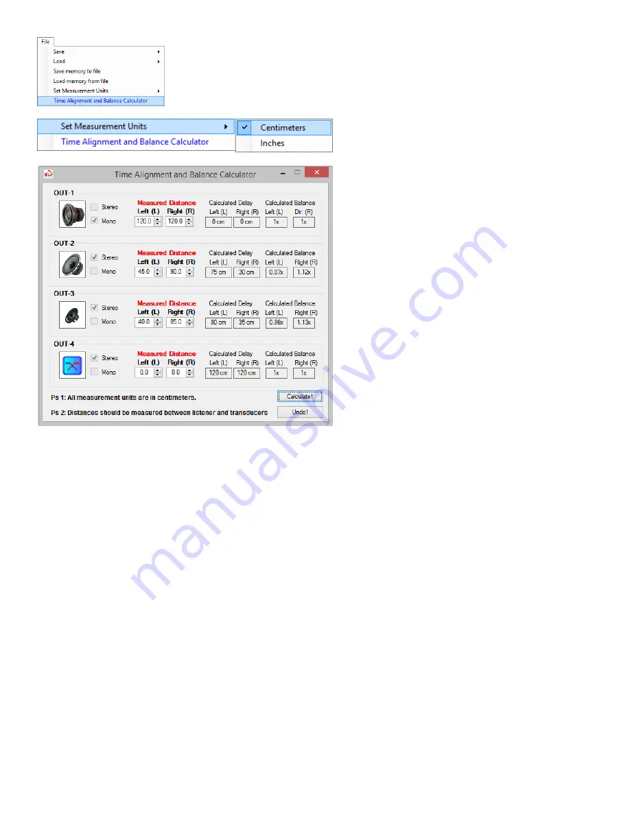
A simple and effective way to 

perform Time Alignment and Balance 
correction 

is available by utilizing the 

calculator built-in the software.  
 
Beforehand, please set your preferred 
measurement unit. You can choose to 
enter measured distances in Inches 
(USA) or Centimeters (other countries). 


Go to: 

File 

 Set Measurement Units. 

Then proceed opening the calculator. Go 
to: 

File 

 Time Alignment and Balance 

Calculator. 
 

Now, all you have to do is to sit as the 
driver and measure the distances 
between you facing forward and the 
transducers (speakers) in your car.  

By using Time Alignment correction, CORE-1 digitally compensates 
for these differences in distance, leading to a perfect listening 
experience, as if the speakers where all physically aligned to each 
other.


Содержание CORE-1

Страница 1: ...ble of 4V RMS 12 5Vpp RCA output swing 2 8 Summing Input channels compatible with Low Level High Level input types 3 Bluetooth Audio Streaming with Apt X codec for audiophile audio quality 4 State of...

Страница 2: ...or any type of switch Please consult Power Source Connector 3 Make SURE that your vehicle s battery is fully charged We strongly recommend using a battery charger during the setup process If the batte...

Страница 3: ...E CONTROL LED INDICATORS Memory Slot Indicators Memory Select Button Gain control Knob Limiter Actuation LEDs Power Indicator LEDs SOFTWARE INSTALLATION UTILIZING CORE 1 INPUTS OUTPUTS TAB Master Inpu...

Страница 4: ...y Selecting Remote ON OFF TOP MENU SAVE LOADING settings to from CORE 1 Frequency Response Graph Language Selection COM PORT Selection TROUBLESHOOTING Device Driver Software Amplifiers won t turn ON A...

Страница 5: ...order as shown on the picture bellow Tip Voltage readings can be observed at the Power Manager tab on the software GND Connect to vehicle s ground REM Remote wire input connect to the Head Unit blue w...

Страница 6: ...ou should use with good quality RCA cables as well as compatible with High Level audio which you should use the supplied RCA to High Level adapter cables The inputs are summed which guarantees perfect...

Страница 7: ...m saturating due to the strength of the signal output by CORE 1 In case of hiss or noise please consult Troubleshooting Item 7 MEMORY Select button Use to switch on the fly between the 3 available Mem...

Страница 8: ...h on the unit itself see image above at the right side as well as on the Remote Control unit MEMORY Select button Use to switch on the fly between the 3 available Memory slots Once you have successful...

Страница 9: ...If battery voltage level is very low LED s become Red for selected actions other than shutdown or if the Power Manager shuts down the remote output s the corresponding LED s will be OFF GAIN CONTROL k...

Страница 10: ...SOFTWARE INSTALLATION Step 1 Please install the CORE 1 Software by advancing through the installation process as indicated...

Страница 11: ...of the first installation part Following that automatically another installer window will open to install the necessary Microsoft NET Chart Control component Please advance through the installation p...

Страница 12: ...d Ready to use If Power LEDs aren t solid green please consult the Troubleshooting Item 5 Step 3 Once CORE 1 has finished initializing please make sure that the CORE 1 software has been successfully i...

Страница 13: ...he available COM port will vary according to the USB port you chose on your computer Each time you choose a different USB port the USB Device Driver will be reinstalled and a different COM port will a...

Страница 14: ...Speaker type selection Output type and phase Stage Depth widening effect optional Remote Control gain knob group s assignment For example if the RCA Output of your Head Unit is capable of 2Vrms it wil...

Страница 15: ...works as a volume control It controls the signal amplitude on each corresponding output group thus controlling the signal intensity that the amplifier receives from CORE 1 Once you have selected the t...

Страница 16: ...n simultaneously apply the desired amount of delay distance to the chosen output groups To exemplify imagine that you have Mid Ranges on GROUP 3 and Tweeters on GROUP 4 Let s assume that your Mid Rang...

Страница 17: ...th 12 dB oct blue the curve is smoother thus less low frequency speaker protection In the other hand 48dB oct orange the curve is very sharp which offers excellent protection but may not be very ear c...

Страница 18: ...configuration and dual voice coil subwoofers When utilizing dual voice coil subwoofers if you by accident choose one of the L R or L R configurations the polarity of the voice coils will be reversed...

Страница 19: ...beyond the maximum limit Xmax 3 Control the amount of output power of the amplifier thus preventing overheating 4 Set limit to how abused the sound system can be 5 Set limit to maximum possible SPL ou...

Страница 20: ...A total of up to 96 parametric equalizer bands possible These equalizer modules are exceptionally efficient because they operate strictly within the output frequency range of the output group which wa...

Страница 21: ...s affected thus giving the impression of a very responsive effective equalization The lower the value the lower is the extension of neighbor frequencies affected thus making the EQ Band more accurate...

Страница 22: ...e above Bandwidth Hi Shelf It is a shelving filter based on the Frequency parameter Bandwidth is ignored As the boost cut is gradually applied to frequencies ahead of the chosen frequency till the top...

Страница 23: ...Manager groups that operate fully independent from each other allowing for an unprecedent level of control over your sound system installation Battery 1 Main and Battery 2 Auxiliary corresponds to an...

Страница 24: ...ry Low Battery conditions are set properly Settings will vary according to the brand model of your vehicle battery and ultimately car audio components By default the voltage levels suggested by CORE 1...

Страница 25: ...nently store onto the non volatile CORE 1 s memory meaning that even if you disconnect the battery you will not loose any of your configurations Likewise you can always load your settings from CORE1 a...

Страница 26: ...ments interact with each other always resulting in an unique combination The graph corresponds directly to the signals being processed by Core 1 In other words it translates what is happening inside t...

Страница 27: ...l display the COM ports available It will vary according to your computer model and the USB port you choose You may as well have another type of device that utilizes a COM Port connection like a matri...

Страница 28: ...TROUBLESHOOTING...

Страница 29: ...driver software for CORE 1 unit However if this process fails for any reason you can always manually install the correct device driver software which is a fairly easy and straightforward process 1 Ope...

Страница 30: ...3 Right click on the CDC RS 232 Emulation Demo and select Update Driver Software 4 Choose Browse my computer for driver software...

Страница 31: ...5 Click Browse and locate the path C Program Files x86 Massive Audio Driver...

Страница 32: ...6 Make sure that the correct path was chosen and click Next 7 Wait for installation to complete and click Close...

Страница 33: ...ort The COM name will vary from computer to computer so don t worry about that CORE 1sucessfully listed on Windows Device Manager as a USB Serial Port 9 You should now be able to see the COM Port by c...

Страница 34: ...idered the Low Battery condition and the CORE 1 leds will be Orange If the battery voltage level drops to equal or less than 11V CORE1 will automatically shutdown the Remote Outputs thus the power amp...

Страница 35: ...are connected to the Remote Outputs of CORE 1 rather than directly to the head unit The CORE 1 manages the remote of the amplifiers so they are powered ON OFF in the correct sequence along with CORE 1...

Страница 36: ...Typical original wiring diagram factory unmodified Modified wiring diagram with Dummy Load resistors and speaker wire to RCA converter...

Страница 37: ...ialization process 11 Bluetooth Audio volume is much louder or much lower than the Head Unit s 12 Bluetooth Audio sounds noisy SOLUTION Make sure the Bluetooth Audio Volume is set to a balanced level...

Отзывы: