8
#
"
Disconnect the engine from the unit by removing
the belt guard, the drive belt, the belt tensioning
spring, and the two engine pivot bolts.
"
1. Remove the 3½” pulley from the rotor
assembly by first removing the circlip, then
loosening the boss screw and withdrawing the
pulley using a puller. Penetrene injected
through the boss screw hole may assist
removal.
2. Remove the shredder chute.
3. Remove the 13mm screw from the end of the
rotor shaft adjacent to the chipper tube.
4. Take the four nuts from the bearing screws.
5. Loosen all four bearing boss screws using a
1
/
8
” Allen key.
6. With a brass (or similar) drift, drive the
shredder shaft partially through the bearing on
the chipper tube side of the machine.
7. Remove the bearing on the pulley side of the
machine using a puller.
8. Remove the chipper blade or ensure that the
blade is nowhere near the chipper tube.
9. Tap the rotor shaft from the pulley side using
a soft hammer. Be careful not to damage the
chipper blade.
10. Remove the bearing on the chipper tube side
of the machine using a puller.
11. The rotor assembly can now be removed by
disconnecting one of the side plates from the
machine.
NOTE: When reassembling, put Loctite 262
(or similar) on the pulley boss screw and
always ensure that a good circlip is fitted.
1. Remove the belt guard.
2. Disconnect the spark plug lead from the spark
plug.
3. Loosen the four engine mounting bolts and
slide the engine forward.
4. Raise the engine and remove the belt.
5. When a new belt is installed, readjust the
engine position so that it is level when the belt
is tight.
6. Attach the belt guard.
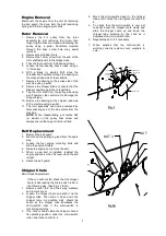
Micro-Switch Adjustment
If the m/c will not start check that the chipper
chute is depressing the micro-switch roller in
the following way: (See Figs. 3 & 3A.)
1. Remove nuts 1& 2 and the spring washers
and remove cover.
2. Loosen the chipper chute and slide it up the
chipper tube. Then slide it back down the
chipper tube. An audible ‘click’ should be
heard as the chipper tube depresses the
micro-switch roller if the micro-switch is
functioning correctly.
3. If no ‘click’ is heard clamp the chipper chute in
its operating position, under the micro-switch
roller, and loosen nuts 3 & 4.
4. Move the micro-switch closer to the chipper
tube until it 'clicks' then re-tighten the nuts 3 &
4.
5. To check that the micro-switch is now set
correctly loosen the chipper chute clamp and
slide the chipper chute up and down the
chipper tube listening for the ‘click’ as it
depresses the micro-switch roller.
6. Repeat steps 3 to 5 if necessary.
7. When satisfied that the micro-switch is
working correctly replace cover, washers &
nuts.
NUT 4
NUT 3
NUT 1
NUT 2
SPRING
WASHER
COVER
MICRO SWITCH
MICRO SWITCH
ROLLER
CHIPPER TUBE
Fig. 3
NUT 4
NUT 3
NUT 1
COVER
Fig.3A


