


6
5. Close the suction and discharge exits with gasket
6. Spray an anti-corrosive into the pump casing.
7. Rotate the pump shaft by hand once in every month, in
order to protect it from freezing and to lubricate the
bearings.
5. ASSEMBLY / INSTALLATION
5.1. Installation
The pump should be installed with the motor shaft vertical.
Ensure that an adequate supply of cool air reaches the
motor cooling fun. Arrows on the pump base show the
direction of flow of liquid through the pump.
Counter flanges, gaskets, bolts, rigid coupling sets are
available as accessories and have to be ordered separately.
Rigid coupling sets are available with threaded sockets or
sockets for welding. Isolating valves should be fitted either
side of the pump to prevent the system being drained if it is
necessary to clean, repare or replace the pump.
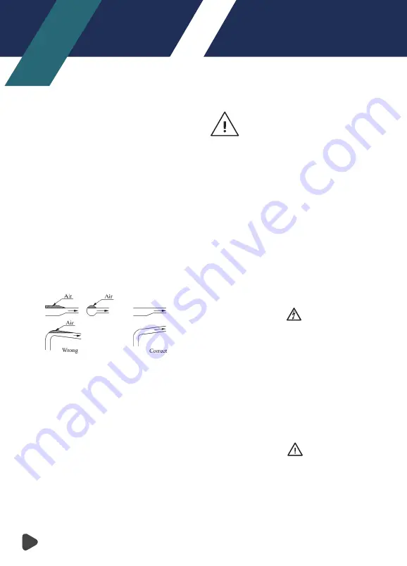
Install the pipes in such a way that air locks are avoided,
especially on the suction side of pump. Correct Pipework
shown in Figure 1.
Figure 1:
Section Conditions
Care should be taken while fitting the pipes so that any
tension coused by variations in temperature does not
affect the pump.
If the pump is installed with long pipes, these should be
adequately supported before and after the pump.
If there is any risk of the pump being choked by sediments
leaves, twigs, etc. measures should be taken to prevent
this, a strainer should be fitted at the suction side of the
pump.
In the case of installations in which the discharge pipe has
been installed horizontally, or it slopes downwards away
from the pump, which can or must be drained in certain
periods, the pump should be protected against dry-run-
ning. This can be done by fitting a loop with a vacuum valve
close to the pump.
The highest point of the loop should at least be in level with
the lower edge of the pump motor.
The discharge pipe can then be drained independently of
the pump and vice versa.
The pump should not be run with a closed
discharge value as this will cause an increase
in temperature/formation of steam in the
pump which may cause damage to the pump.
If there is
any danger of the pump running with a closed discharge
valve, a minimum liquid flow through the pump should be
ensured by connecting a bypass/a drain to the discharge
pipe. The drain can be connected to a tank.
5.2. Electrical Connection
• The electrical connections should be carried out by a
qualified electrician.
• To make sure the motor is suitable for the power supply;
cables of the motor must be connected to power supply
according to the figure on the terminal box and the motor
nameplate.
• Motor shall be connected with a fast and effective motor
starter, to ensure that the motor will not be damaged by
lack of phase, unstable voltage or overload. The motor
shall earth reliably.
CAUTION
Before take apart the terminal box cover or dismantle
pump, make sure that the power supply is switched off.
Warning – Electrical connection and safety devices
• The pump units should be connected to the power supply
by the appropriately rated power cables according to the
motor ratings.
• The pump units should always be equipped with safety
devices as required in the standards (EN 809 and/or
EN60204-1) as well as by the national rules of the country
where the pump is used.
• Despite the rules of any country, the power supply to the
pump unit must be equipped with at least following
electrical safety devices with appropriate ratings:
- Emergency switch
- Circuit breaker (as a supply disconnecting (isolating)
device as well as an over current protective device)
- Motor overload protection
Do not start the pump until it has been filled with liquid.
6. COMMISSIONING, START UP AND OPERATING
CAUTION
It is prohibited to run without liquid, which will damage
mechanical seal and sliding bearing.
Содержание HEXA 1
Страница 1: ...Operating Manual July 2020 Revision No 01 HEXA SERIES Vertical Shaft Stainless Steel Pumps...
Страница 2: ...2...
Страница 13: ...NOTES...
Страница 14: ...NOTES...
Страница 15: ...NOTES...