background image

6

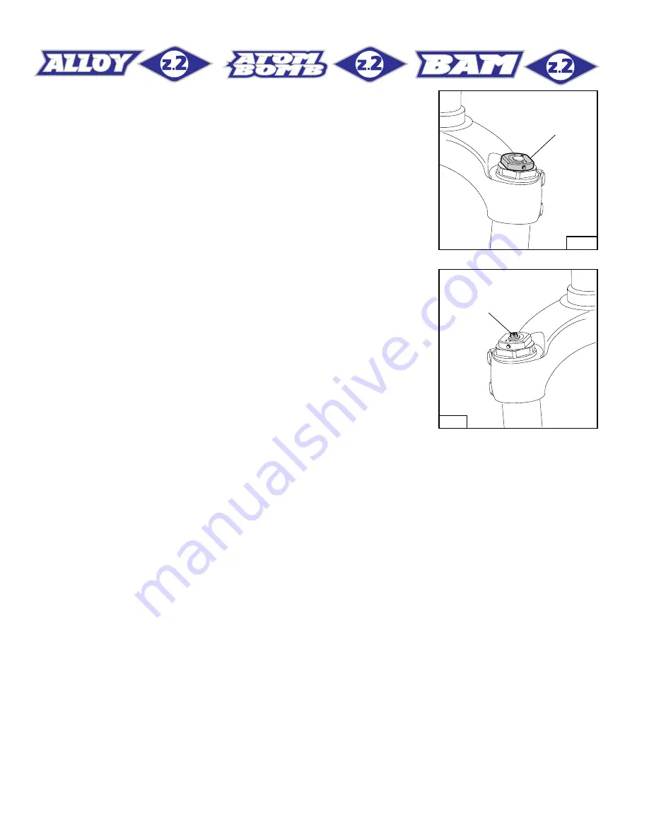
SPRING PRELOAD (FIG. B)
The spring preload determines COMPRESSION damping and can be
adjusted by turning the knob (2) on top of the fork legs. From the factory
the Z2 is set with the minimum preload, i.e. the adjustment knob is
completely unscrewed counterclockwise. However, the springs are
slightly preloaded to help counteract static loads. By turning the
adjustment knob clockwise, the preload is increased up to the maxi-
mum value equal to 15 mm’s of spring preload. This adjustment is
essential in order to have the right  Z2 response for the rider’s weight
and riding style.

REBOUND & COMPRESSION
ADJUSTMENT (FIG. C)
The right fork leg is equipped with an adjuster screw (A) for damping.
When turning this adjuster clockwise into the cartridge rod, the damping
for compression & rebound increases. In short, the amount of adjust-
ment applied on the piston in the fluid determines the rate of compres-
sion & rebound damping. To adjust, always start from the minimum
damping setting, i.e. unscrew completely counterclockwise. Adjust-
ment range is about 8 turns – i.e. abt. 4 mm.

2

Left

FIG. B

A

Right

FIG. C

DISASSEMBLY

GENERAL
– The reference numbers given in this section relate to the components shown in the forks exploded view on page 15-16-17.
– These operations refer to the fork legs having already been removed from the crown and disassembled from the brake arch.
-– Before starting any operation, please read the diagram below. It shows the quickest procedure and the exact sequence in which it should be

disassembled. Locate the part you need to remove in the diagram, then look at the arrows to determine which other parts you will need to remove
first.

Содержание Bomber Z1 BAM

Страница 1: ...CE 1949 SINCE 1949 SINCE 1949 FI F T Y Y E A R S OF S US PEN S I O N I N N O VATI O N FI F T Y Y E A R S OF S US PEN S I O N I N N O VATI O N ...

Страница 2: ...rs may not have been adjusted at the time the Marzocchi suspension system was installed on the bicycle Before you ride the bicycle be sure all the parts of the bicycle were properly adjusted and functioning properly 3 All of the components of the suspension system must be correctly assembled and tightened exactly to the specified torque values Periodically check the torque of these components to i...

Страница 3: ...ing Seals Computer designed oil seals guarantee the highest quality seals available Oil Specially formulated oil which eliminates foaming and viscosity breakdown while providing complete stiction free performance Fork leg oil type EBH 16 SAE 7 5 Z2 ATOM BOMB right leg 75 cc left leg 85 cc Z2 BAM right leg 90 cc left leg 100 cc BAM Bomber Aerospace Material Special alloy developed from aerospace ma...

Страница 4: ...t of the wrenches in metric size FAILURES CAUSES AND REMEDIES This paragraph reports some failures that may occur when using the fork It also indicates possible causes and suggests a remedy Always refer to this table before doing any repair work Excessive play of stanchions in the sliders Replace pilot bushings Pilot bushings are worn Replace hydraulic cartridge Cartridge is faulty Fork rebounds t...

Страница 5: ...ion of the steer tube into the crown the rider might lose control of his her bicycle thus jeopardizing his her safety Check the torque of the bolts fastening the stanchions to the crown and attaching the arch to the sliders For recommended torque settings see the table below DISC BRAKE SYSTEM ASSEMBLY Assembling the brake caliper onto the slider is a very delicate operation that should be carried ...

Страница 6: ...iseintothecartridgerod thedamping for compression rebound increases In short the amount of adjust ment applied on the piston in the fluid determines the rate of compres sion rebound damping To adjust always start from the minimum damping setting i e unscrew completely counterclockwise Adjust ment range is about 8 turns i e abt 4 mm 2 Left FIG B A Right FIG C DISASSEMBLY GENERAL The reference numbe...

Страница 7: ...SEAL ASSEMBLY CHANGE STANCHION TUBE FIG 7 DUST SEAL FIG 9 STOP RING FIG 10 OIL SEAL FIG 11 UPPER WASHER FIG 12 PILOT BUSHING FIG 13 PUMPING ROD FIG 8 REBOUND STOP RUBBER FIG 8 REBOUND SPRING FIG 6 DISASSEMBLY DIAGRAM SPRING CHANGE FIG 1 Move the knob 2 to the minimum preload position Loosen the small Allen bolt 3 fastening the preload knob by means of a 1 5 mm Allen wrench Remove the knob from the...

Страница 8: ...IG 4 Push the stanchion tube into the slider and remove the spring 9 Let all the oil drain into the fork leg By following this procedure there is no need to check the oil level Make all necessary changes HYDRAULIC CARTRIDGE CHANGE right fork leg only FIG 5 Let all the oil drain out WARNING Remember to always recycle any used oil To change the fork leg oil follow the procedure as described in secti...

Страница 9: ...lace the whole hydraulic cartridge PILOT BUSHING AND SEAL ASSEMBLY CHANGE FIG 7 Pull the stanchion tube 13 completely out of the slider FIG 8 A pumping rod 36 complete with rebound spring 12 is fitted into the L H leg inside the stanchion Withdraw the above parts from the tube top FIG 9 Use a small screwdriver and remove the dust seal 14 from the slider ...

Страница 10: ...ts seat FIG 11 Fit the slider protector A onto the slider and remove the oil seal 16 with the help of a large slot screwdriver IMPORTANT when removing the oil seal make sure not to damage its seat Once removed the oil seals should not be used again FIG 12 Remove the upper washer 17 from the slider FIG 13 Fit the bit of a small screwdriver into the upper edge slot of the pilot bushing 18 and lift g...

Страница 11: ...n slider and bushing Insert the pilot bushing 18 into place so that it adheres to the slider FIG 15 Fit the upper washer 17 into the slider so that it touches the pilot bushing FIG 16 Lubricate the oil seal 16 and place it onto the seal press B with the hollow side toward the slider Press the oil seal into place until it touches the lower washer by using the above seal press 15 FIG 17 FIG 17 Inser...

Страница 12: ...ide play In the event it is too hard or too soft repeat the previous steps described above and check components to ensure they are not damaged HYDRAULIC CARTRIDGE right leg AND PUMPING ROD left leg FIG 20 Push the stanchion up to slider bottom Fitthehydrauliccartridge 11 completewiththereboundspringintothe R H stanchion and push until it reaches the bottom Fit the pumping rod 36 completewithreboun...

Страница 13: ...ecommended distance H from the top of the stanchion tube SPRING AND CAP FIG 23 Fit the spring 9 into the stanchion tube Move the preload adjuster 7 in the cap to the minimum preload position Lubricate the O ring 10 on the top of the preload knob support right slider only and the O ring 6 on the cap 5 FIG 24 right leg only Screw the cap 5 complete with preload adjuster 7 and lower washer 8 onto the...

Страница 14: ...and make sure it is properly seated into place FIG 27 Fit the preload knob 2 and secure it on the support by tightening the Allen bolt 3 at 1 5 Nm At this point the brake arch can be assembled with the fork legs which should be fitted onto the crown as specified in section INSTALLA TION ...

Страница 15: ... bushing 19 R H slider 20 L H slider 21 O ring 22 Foot nut 23 Cantilever boss 24 Arch 25 Screw 26 Brake cable support 27 Screw 28 Brake cable support kit 29 R H sticker 30 L H sticker 31 Crown with steer tube 32 Screw 33 Crown 34 Steer tube 35 Internal preload adjuster 36 Pumping rod 37 Stanchion protections 38 Sticker 32 33 34 32 12 13 6 14 15 16 17 18 19 22 21 22 21 1 2 7 8 9 9 36 12 13 14 15 16...

Страница 16: ...H slider 20 L H slider 21 O ring 22 Foot nut 23 Cantilever boss 24 Arch 25 Screw 26 Brake cable support 27 Screw 28 Brake cable support kit 29 R H sticker 30 L H sticker 31 Crown with steer tube 32 Screw 33 Crown 34 Steer tube 35 Internal preload adjuster 36 Pumping element 37 Stanchion protections 38 Sticker 32 33 34 32 38 30 29 12 13 6 14 15 16 17 18 19 22 21 22 21 1 2 7 8 9 9 36 12 13 14 15 16 ...

Страница 17: ...er 8 Lower washer 9 Spring 10 O ring 11 Hydraulic cartridge 12 Rebound spring 13 Stanchion tube 14 Dust seal 15 Stop ring 16 Oil seal 17 Upper washer 18 Pilot bushing 19 R H slider 20 L H slider 21 O ring 22 Foot nut 23 Cantilever boss 24 Arch 25 Screw 26 Brake cable support 27 Screw 28 Brake cable support kit 29 R H sticker 30 L H sticker 31 Crown with steer tube 32 Screw 33 Crown 34 Steer tube 3...

Отзывы: