background image


17


FILTER CONFIGURATION SUBMENU 


  False Colors 


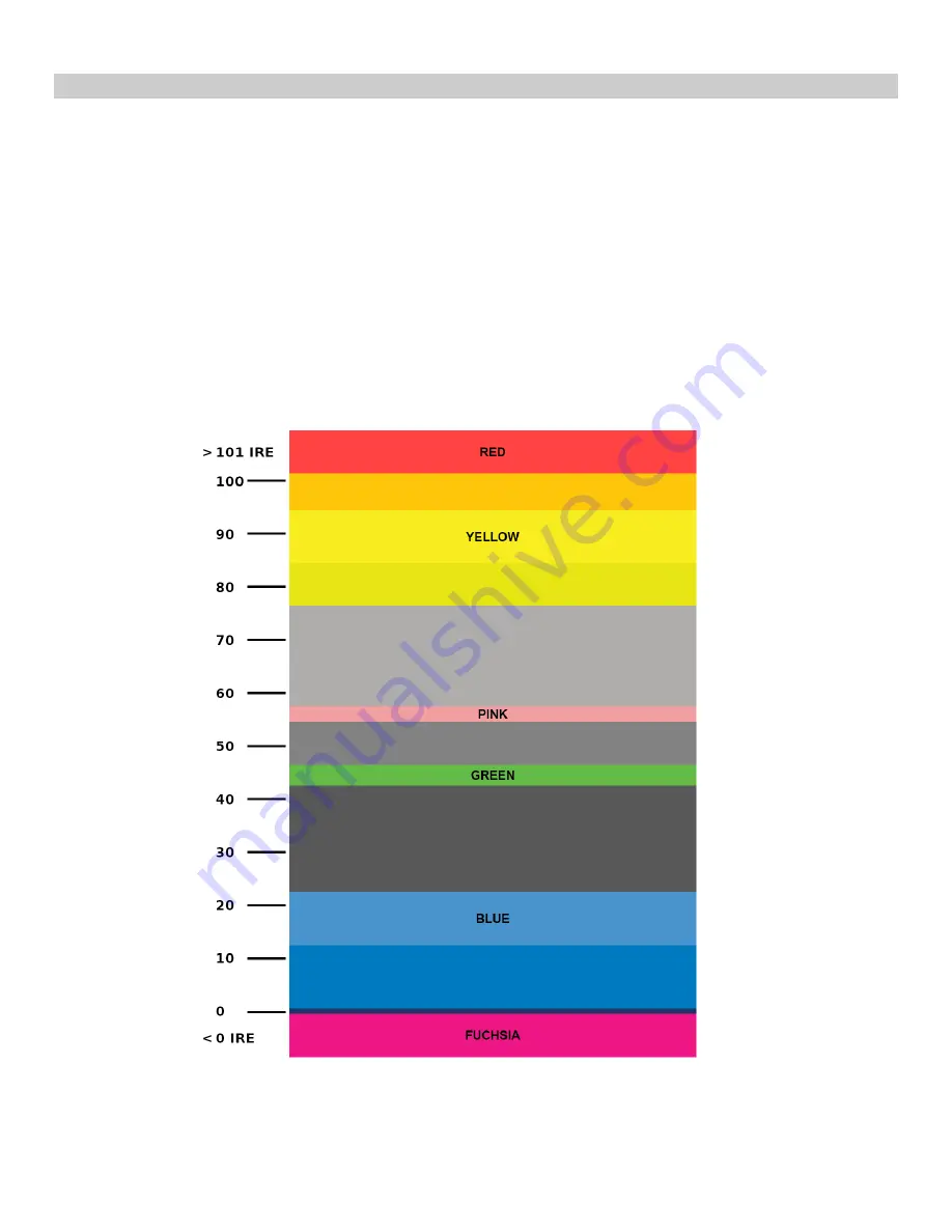
The V-LCD651STX has a false color filter to aid in the setting of camera exposure. As the camera Iris is adjusted, 
elements of the image will change color based on the luminance or brightness values. This enables proper exposure to 
be achieved without the use of costly, complicated external equipment.  To best utilize this feature, you must 
understand the color chart below and have a basic understanding of camera exposure. Normally, when shooting 
subjects like people, it is common practice to set exposure of faces to the equivalent of approximately 56 IRE. The 
false color filter will show this area as the color PINK on the monitor. Therefore, as you increase exposure (open the 
IRIS), your subject will change color as indicated on the chart: PINK, then GREY, then a few shades of YELLOW. Over 
exposed subjects (above 101 IRE) on the monitor will be shown as RED. In addition, underexposed subjects will show 
as DEEP-BLUE to DARK–BLUE, with clipped-blacks indicated with a FUCHSIA-like color. Lastly, the color GREEN is 
used to indicate elements of the image that are approximately 45 IRE. This represents a ‘neutral’ or ‘mid-level’ 
exposure commonly used for objects (not people).  


False Color Key 

Содержание V-LCD651STX-3GSDI

Страница 1: ...Marshall Electronics Model No V LCD651STX HDA Model No V LCD651STX HDI Model No V LCD651STX 3GSDI 6 5 High Resolution Super Transflective Field Monitor Operating Instructions ...

Страница 2: ...2 ...

Страница 3: ...es 7 Compatible Input Formats 8 On Screen Menu 9 MAIN MENU AND NAVIGATION 10 VIDEO CONFIGURATION SUBMENU 10 MARKER CONFIGURATION SUBMENU 14 FILTER CONFIGURATION SUBMENU 17 SYSTEM CONFIGURATION SUBMENU 18 FUNCTION PRESETS SUBMENU 19 SYSTEM INFORMATION SUBMENU 20 Specifications 21 Dimensions 22 Maintenance 23 Warranty 23 ...

Страница 4: ...well in sunlight or indoors under direct studio lighting Multi Format Compatibility The V LCD651STX accommodates many video standards with Composite Video and YPbPr inputs Accepted formats include NTSC PAL 480i p 576i p 720p and1080i The HDMI version of the V LCD651STX accepts digital video inputs and standard VESA formats The 3G SDI version includes a triple rate SDI input accepting SDI HD SDI an...

Страница 5: ...Monitor V PS12 5V XLR Power Supply with 4 Pin Female XLR Connector Operating Instructions Inspect the unit for any physical damage that may have occurred during shipping Should there be any damage immediately call Marshall Electronics Customer Service at 800 800 6608 If you are not located within the continental United States call 1 310 333 0606 ...

Страница 6: ...uttons to display and navigate the on screen menu Image Adjustment Knobs Use the image adjustment knobs to adjust brightness color saturation and contrast of the image The status of each image adjustment parameter is shown on the bottom left of the screen with values ranging from 0 to 100 Default value is 50 Tint will adjust the hue of Composite inputs only Power Switch Use the hard power switch t...

Страница 7: ...upplied from the included power supply or from a variety of DC sources supplying at least 1 Amp at 12 Volts IMPORTANT If using a power source other than the included power supply be sure that the polarity of the DC input is correct Pin 1 GND Pin 2 N C Pin 3 N C Pin 4 12VDC Battery Adapter The V LCD651STX HDI can be powered from a variety of batteries Several user interchangeable battery adapters a...

Страница 8: ...576i 50 HD SDI 720p 60 59 94 50 30 29 97 25 1080i 60 59 94 50 1080p 30 29 97 25 24 24sF 23 98 23 98sF 3G SDI YCbCr 4 2 2 10 Bit Level A and B 1080p 60 59 94 50 YCbCr RGB 4 4 4 10 Bit Level A and B 1080i 60 59 94 50 1080p 30 29 97 29 97sF 25 25sF 24 24sF 23 98 23 98sF V LCD651STX HDI V LCD651STX monitor with HDMI Input HDMI Video 720p 60 59 94 50 30 29 97 25 1080i 60 59 94 50 1080p 30 29 97 25 24 2...

Страница 9: ...bCr RGB System Configuration HDMI Aspect Ratio Manual Auto Function on F1 Ratio Check Field Level Sensor Mosquito Filter Peaking Filter False Colors Freeze Input Aspect Markers Center Marker Marker Enable Underscan H V Delay Pixel to Pixel Function Presets Function on F2 Ratio Check Field Level Sensor Mosquito Filter Peaking Filter False Colors Freeze Input Aspect Markers Center Marker Marker Enab...

Страница 10: ...e monitor s color balance R G B This should only be done by someone experienced with video engineering as this will alter the overall color shading of the screen The purpose is to allow color matching to other types of monitors and or displays Note The Color Temperature preset will automatically switch to USER when Color Bias settings are adjusted It is normal for color bias adjustments to be very...

Страница 11: ...pattern super black black and gray bars at the lower right corner of the screen Adjust the Brightness knob until there is no visible difference between the super black and black bars but the gray bar is still visible 5 Adjust the Contrast knob until an even grayscale appears along the top bars 6 Disable Monochrome mode 7 Enable Blue Check Field mode and adjust the Color knob so that the outermost ...

Страница 12: ...sary LCD pixels For example NTSC images will occupy exactly 720 x 480 pixels The surrounding pixels will be black For incoming formats exceeding 1024 x 768 pixels only the center 1024 x 768 of the incoming image will displayed occupying the whole screen with the remainder of the picture cropped For example 1080i formats will both be cropped to 1024 x 768 and displayed full screen Note Pixel to Pix...

Страница 13: ...n Underscan Use this setting to enable or disable Underscan mode When Underscan is OFF the active portion of the video signal is displayed on the screen with 0 overscan When Underscan is ON the image size is slightly reduced This allows the user to clearly view the edges of the active video area NTSC Black Level Set the NTSC Black Level according to the type of NTSC composite video input 7 5 IRE U...

Страница 14: ...Center Marker Use this setting to display a center marker on the screen 16 9 Markers Use these settings to superimpose one of 12 markers on the screen when in Full Screen mode or 16 9 mode 4 3 13 9 14 9 1 85 1 2 35 1 95 Safe 93 Safe 90 Safe 88 Safe 85 Safe 80 Safe User 16 9 Marker Examples Marker Configuration Submenu 90 Safe Area OFF No Marker 4 3 Aspect Ratio Marker 2 35 1 Aspect Ratio ...

Страница 15: ...r 16 9 in the Marker Configuration submenu and press the SELECT button You may also begin with an already predefined safe area 95 93 90 etc and make your adjustments from there by highlighting a particular safe area and pressing the SELECT button 2 Use the BRIGHT COLOR TINT and CONTRAST knobs to move the LEFT RIGHT TOP and BOTTOM borders of the safe area to your desired position When you have reac...

Страница 16: ...ed on the complete image 25 Image area beyond the marker is shown at 25 intensity 50 Image area beyond the marker is shown at 50 intensity 75 Image area beyond the marker is shown at 75 intensity 100 Image area beyond the marker is shown at 100 intensity black Example 80 Marker in 4 3 Mode Normal Background Black Background ...

Страница 17: ... it is common practice to set exposure of faces to the equivalent of approximately 56 IRE The false color filter will show this area as the color PINK on the monitor Therefore as you increase exposure open the IRIS your subject will change color as indicated on the chart PINK then GREY then a few shades of YELLOW Over exposed subjects above 101 IRE on the monitor will be shown as RED In addition u...

Страница 18: ...ing to filter out Mosquito Noise an artifact that appears as specs around edges of objects This artifact is the result of video that has been compressed at some point Video sources from DVD Players PDA s Digital Cable Boxes Camcorders etc often have this artifact SYSTEM CONFIGURATION SUBMENU System Configuration Submenu Input Format OSD Use this option to enable on screen display of input format s...

Страница 19: ...o settings of incoming HDMI video Most HD signals will display in the 16 9 aspect ratio SD signals 480P 576P will display in the 4 3 aspect ratio FUNCTION PRESETS SUBMENU User Definable Function Buttons Use the Function on F1 F2 F3 and F4 menu items to define each function button on the front panel of the monitor The following options are available for each button Ratio Check Field Level Sensor Mo...

Страница 20: ...SUBMENU System This shows the System firmware version of your monitor Keypad This shows the Keypad firmware version of your monitor Module This shows your module version HDMI or 3GSDI and the firmware version of your module ...

Страница 21: ...Power Consumption 1 25 Amp Max 12VDC 16W Max Voltage Requirement 12VDC 7VDC 20VDC V PS12 5V XLR Power Supply Input 100V 240V 1 5A 50 60Hz Output 12VDC 5A 60W Max BATTERY ADAPTER Field Interchangeable Battery Adapter Options Sold Separately Marshall Adapter Battery Type Battery Voltage Recommended Battery CM Canon 7 4 V Canon BP 970G PM Panasonic 7 2 V Panasonic CGA D54 JM JVC 7 2 V JVC BN V438U SB...

Страница 22: ...22 Dimensions ...

Страница 23: ...l container for a period of one year from the purchase date This warranty is extended to the first consumer only and proof of purchase is necessary to honor the warranty If there is no proof of purchase provided with a warranty claim Marshall Electronics reserves the right not to honor the warranty set forth above Therefore labor and parts may be charged to the consumer This warranty does not appl...

Страница 24: ...24 2010 0512 Marshall Electronics Inc 1910 East Maple Ave El Segundo CA 90245 Tel 800 800 6608 310 333 0606 Fax 310 333 0688 www LCDRacks com sales lcdracks com ...

Отзывы: