18
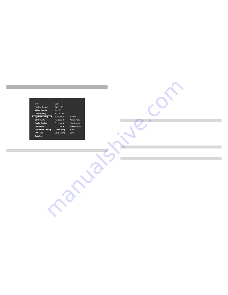
System Configuration Submenu
Use the System Configuration submenu to control various system parameters such as GPI, function button settings and
User definable presets.
■
Green, Red and Yellow GPI
Use the Green, Red and Yellow GPI menu items to set a certain action when the Green, Red or Yellow tally connector is
activated through dry contact on the tally connector on the back of the unit. The following options are available for each
input:
.
•Tally
Activate the Green, Red or Yellow On Screen Tally
•Monochrome
Activate Monochrome mode
•Blue Only
Active Blue Only mode
•Pixel to Pixel
Activate Pixel to Pixel
•Anc. Monitor
Activate the Ancillary data monitor
•OSD Tally
Activate the OSD Tally
•IMD State
Activate IMD Text Strings on the screen
•CTemp / Gamma
Toggle through the different CTemp settings
•Layout
Toggle through the available screen Layouts
•Aspect Ratio
Toggle through the available Aspect Ratios
•Anc. Timecode
Toggle through the Ancillary Timecode options
•Marker Level
Toggle through the available Marker background options
•Monochrome (L)
Activate the Monochrome function when the Tally pin is set to LOW (dry contact)
•Markers (L)
Toggle through the available Markers when the Tally pin is set to LOW (dry contact)
•Marker Mask 50% (L) Activate the 50% Marker Mask when the Tally pin is set to LOW (dry contact)
•Marker Mask Black (L) Activate the Black Marker Mask when the Tally pin is set to LOW (dry contact)
•Marker Center (L)
Activate the Center Marker when the Tally pin is set to LOW (dry contact)
System Configuration Submenu
15
1.
Allow the monitor to warm up for at least 5-10 minutes.
2.
Display SMPTE split-field color bars on the monitor using an external source.
3.
Enable Monochrome mode.
4.
Locate the pluge pattern (super black, black, and gray bars) at the lower-right corner of the screen. Adjust the
Brightness knob until there is no visible difference between the super black and black bars, but the gray bar is still visible.
5.
Adjust the Contrast knob until an even grayscale appears along the top bars.
6.
Disable Monochrome mode.
Enable Blue-Only mode and adjust the Color knob so that the outermost bars (white and blue) appear to match in
brightness.
■
Pixel-to-Pixel Mode
Use this setting to enable Pixel-to-Pixel mode.
This mode bypasses the monitor’s internal scaling function and displays images in their native resolution and aspect ratio,
with a one-to-one mapping of incoming image pixels to screen pixels:
•
For incoming formats smaller than the native resolution of the window (or selected aspect ratio), the image will be
displayed in the center of the window using only the necessary LCD pixels. For example, 480i images will only occupy
exactly 640x480 pixels in a particular channel window in Quad mode, or if the channel is selected full screen, it will occupy
exactly 640x480 pixels in the center of the screen. The surrounding screen area will be black.
■
Curtain Color
Use this setting to choose the default color displayed on the screen when no video input is present. Available colors are
red, green, white, black and blue.
■
Aspect Ratio Settings
Use this menu option to switch between several aspect ratio settings.
•
In 4:3 mode, images are scaled up or down to fill the maximum 4:3 portion of the screen. IMD text and time code
are superimposed on the lower portion of the image. The audio presence indicator and on-screen tally are displayed at
the bottom of the screen, outside the image.
•
In Scaled 4:3 mode, images are scaled to a smaller 4:3 portion of the screen, leaving space for IMD text, tally,
and audio presence indicator to be displayed below or around the image. Time code is superimposed on the lower portion
of the image.
•
In 16:9 mode, images are scaled to fill the maximum 16:9 portion at the top of the screen. In this mode, IMD text
and on-screen tally are displayed below the image. Time code and the audio presence indicator are superimposed on the
lower portion of the image.
•
In Full Screen mode, images are scaled to fill the entire screen. In this mode, all OSD features are superimposed
on the image.
The diagrams on the following page show how IMD text, timecode, and the audio monitor icon are simultaneously
displayed on the screen in each aspect ratio setting. The white area represents the video image.
Содержание QVW-2710
Страница 2: ...2 Intentionally Left Blank 31...
Страница 3: ...30 Dimensions 3 Intentionally Left Blank...


