background image

10


MPC-ML10DVR-UM(B)  4/2011

SAFETY

General Safety Instructions

•  Before operating the MPC-ML10DVR Monitor, read this User Manual thoroughly
•  Retain this User Manual for future use
•  Verify the computer system capability (see System Set-up) to insure operation of the 

Monitor

•  For expeditious installation, follow these User Manual instructions in the sequence 

presented

•  Adhere to all Caution and Warnings on system parts and as stated in this User manual
•  All User Manual instructions for installation and operation must be followed precisely
•  Adjust only those controls covered by the User Manual’s operating instructions; im

-

General Unit Safety

•  Always disconnect the unit from the power source before cleaning
•  Do not operate the unit with a damaged cord
•  Do not operate if the unit has been dropped or damaged. The unit needs inspected by 

qualified MarinePC Service Personnel

•  Position the power cord so it shall not be in contact with hot surfaces
•  Do not allow anything to rest on the power cord, and
•  Do not place the power cord where there shall be foot traffic.


General Safety Precautions

•  Power cord must be connected to a properly wired and grounded power source

•  Any equipment to which the unit shall be attached must also be connected to properly 

wired and grounded power sources

•  Do not connect or disconnect the unit during an electrical storm

•  Do not remove the unit covers – there are no user serviceable parts in the unit

•  Do not disassemble or modify the unit to avoid the possibility of electrical shock, 


damage to electrical components or scratching the Display surface, and

•  Disassembly of the unit voids the warranty.

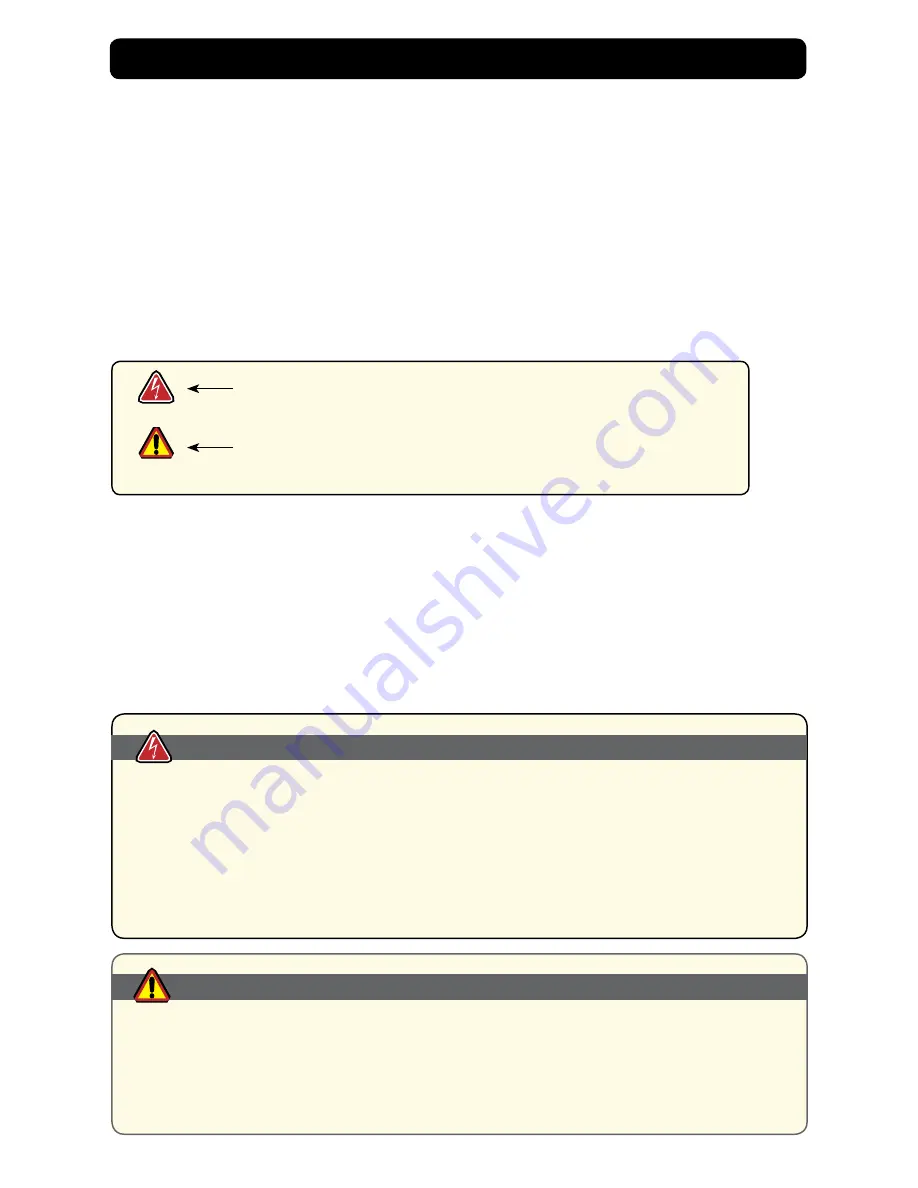
WARNING!

CAUTION!

Warning! Shock Hazards

This icon is intended to tell you of a potential risk of electrical shock.

Caution! Instructional

This icon is intended to tell you of important operating and/or

maintenance instructions. 

Safety Icons

WARNING!


Fluids from LCD Display

•  If the Monitor should ever become shattered, do not touch fluids from an LCD Display

•  If fluid should get on hands or clothing, immediately wipe off with liquid soap or rubbing 

alcohol; wash with water; consult with a doctor, and

•  If fluid gets in the eyes, flush eyes immediately with water for a minimum of 15 minutes; 

consult with a doctor.

CAUTION!

Содержание MPC-ML10DVR

Страница 1: ...MPC ML10DVR Digital Video Recorder LCD Monitor User Manual www MarinePC com N S E W MARINE PC MARINE PC ...

Страница 2: ... out of the use of or the inability to use MarinePC s product or its documentation even if advised of the possibility of such damages Endorsement Product names mentioned herein are used for identification purposes only and may be trademarks and or regis tered trademarks of their respective companies Copyright This document contains proprietary information protected by copyright All rights are rese...

Страница 3: ...MPC ML10DVR UM B 4 2011 3 MPC ML10DVR Military Grade Digital Video Recorder LCD Monitor User Manual www MarinePC com ...

Страница 4: ...ion 9 Safety 10 Product Care and Maintenance 12 System Set up 13 Installation 14 Display Connections 16 Operator Controls 17 On Screen Display 18 Digital Video Recorder 24 Video Gallery 26 Appendix A Overview Drawings 27 Appendix B Troubleshooting 27 Appendix C Technical Specifications 29 ...

Страница 5: ... providing environmental protection and tranportability for the DVR The MPC ML10DVR handles a wide range of severe environments making it the first choice of serious mariners for their demanding applications Designed to be rugged the 800x600 SVGA Resolution Flat Panel Display is engineered to mate perfectly to all leading edge cameras including infrared image amplified and visible spectrum sources...

Страница 6: ...djust to the lowest setting which still allows ease of viewing The last step of the Brightness Down control is Backlight OFF From this last step pressing the Brightness Up button one short time will put the backlight in the lowest possible setting of 1 nit NOTE Using the lowest brightness setting backlight off maintains power to the other internal electronics and keeps them fully functional includ...

Страница 7: ...d and saved and the RECORDING message will disappear from the display Alternately pressing the Stop button marked with a square will also stop the recording This process can be repeated any number of times each time creating a unique wmv file Any number of files can be created A total of 8 hours of files can be recorded If the solid state memory storing the files is already full the DVR will start...

Страница 8: ...s an auxilliary USB cable must be attached to the MPC ML10DVR The cable can be attached to any PC for standard Windows file transfer of the stored avi files in the unit to the computer Once the cable is connected press the Play button The Fast Forward button on the right side now has the DOWN LOAD message shown on the display Press this button and the unit will now be recognized by the PC as a mem...

Страница 9: ...lighting op tion is available that will limit the light used to backlight the display to frequencies not amplified by the NVG s thereby allowing both those using NVG s and those viewing normally to look at the display Alternately some situations require the use of red spectrum lighting to preserve natural night vision As an option the MPC ML10DVR can be configured with NVIS Red to allow for use in...

Страница 10: ...r cord where there shall be foot traffic General Safety Precautions Power cord must be connected to a properly wired and grounded power source Any equipment to which the unit shall be attached must also be connected to properly wired and grounded power sources Do not connect or disconnect the unit during an electrical storm Do not remove the unit covers there are no user serviceable parts in the u...

Страница 11: ...nput voltage is 10 36 VDC MPC ML10DVR power consumption is listed at 6 watts minimum 20 Watts maximum Power Consumption Warning Protection on Servicing Servicing User User Servicing is limited to cleaning the Display Do not disassemble or modify the Display to avoid the possibility of electrical shock damage to its electrical components or scratching the Display surface and Disassembly voids the w...

Страница 12: ... cleaners on the Flat Panel or Touch Screen Display its enclosure or any other electrical device cables power cord etc Do not use paper products as they may scratch the Display screen and Do not directly apply cleaning solutions to the Display screen Turn off the Monitor power before cleaning the Monitor screen or unit s enclo sure warning caution In marine or similar environments an added benefit...

Страница 13: ...Cord warning SYSTEM SET UP System Requirements The MPC ML10DVR accepts a standard NTSC composite video signal from any device a camera DVD or VCR Shipping Box Contents The MPC ML10DVR is shipped in a custom box with custom packaging It is recommend ed that the installer should save box and all packaging materials in case Display should need to be returned to the MarinePC Service Center Shipping bo...

Страница 14: ... angle to improve viewability in changing environments This ball and socket system has proven to be successful in supporting an extreme amount of weight in high vibration and difficult mount applications Visit www marinepccom for product mounting diagrams Locate the ball and socket system in shipping box This kit consists of two RAM balls on mounting plates and a RAM arm with an adjustable T knob ...

Страница 15: ...urface substrates Display will be mounted on installer will provide screws to mount other ball Take care not to strip screw holes or over tighten as the enclosure is aluminum Caution Panel Mount Panel Mount installation should be specified at time of order the ball and socket mount system will not be included in the shipping box Figure 5 For installation there are four tapped mounting holes on fou...

Страница 16: ...nectors USB Connector MPC ML10DVR accepts a USB signal The MIL DTL 38999 Series 1 USB Connector has a 4 pin plug J2 Pin out is indicated in Table 2 Ground A location for chassis bonding ground is available on the rear of enclosure Table 1 Power Video 13 pin PLUG MIL DTL 38999 Series I PIN SIGNAL 1 RS 170 3 SIGNAL 2 RS 170 3 GND 3 RS 170 2 SIGNAL 4 RS 170 2 GND 5 RS 170 1 SIGNAL 6 RS 170 1 GND 7 28...

Страница 17: ...brightness LARGE SUN Button when repeatedly pressed or held down will cause the Display s backlight brightness to step up in increments to its brightest setting SMALL SUN Button when repeatedly pressed or held down will cause the Display s backlight brightness to step down in increments to its lowest setting Control s lowest setting is near total black making it suitable in very subdued light as i...

Страница 18: ...nly there is no text INPUT SELECTION COLOR IMAGE ENHANCEMENT IMAGE SETTINGS TOOLS EXIT Figure 8 General Operating Instructions To open the OSD Menu press once the SELECT Button OSD Menu appears across bottom of Display screen Use UP or DOWN Button to move across Menu selected icon turns yellow Figure 9 As Main Menu icon is highlighted its Submenu appears in OSD dialog box Press once SELECT Button ...

Страница 19: ...play allows for moving through various video input signals without accessing the OSD Menu C Video 1 Select for first Input Signal Select Exit Button to save C Video 2 Select for second Input Signal Select Exit Button to save C Video 3 Select for third Input Signal Select Exit Button to save Input Selection Press once SELECT Button to go to a new menu item Figure 10 or Press once SELECT Button to s...

Страница 20: ...xit Button to save The Image Enhancement Menu enables adjustments of Image Enhancement values Sharpness Select Sharpness to adjust Sharpness of displayed image Use UP right or DOWN left Button to adjust in preset increments Select Exit to save Composite input signal factory default is 33 within a range of 0 100 Black Level Select Black Level to adjust Black Level of input Composite Signal Factory ...

Страница 21: ...y default OSD Timeout setting is 30 seconds Interval selections are Off 5 15 30 and 60 seconds Select to adjust time elapse between last Menu activity and when Menu exits Use the UP increase or DOWN decrease Buttons to change the values Select Exit Button to save Note Any changes made in will be saved upon Timeout Exit Color Reset Select Color Reset to reset active Composite signal Color parameter...

Страница 22: ...to go into Active Mode Use UP or DOWN Arrow Button to set current Month Press SELECT to go into Inactive Mode Use UP or DOWN Arrow Button to move to Days Days are highlighted Press SELECT to go into Active Mode Use UP or DOWN Arrow Button to set current Day Press SELECT to go into Inactive Mode Use UP or DOWN Arrow Button to move to Time Set Military Time Set Time Military Press SELECT to go into ...

Страница 23: ...y Dialog appears Confirm Delete Selected File s now On left bezel locate text Delete All Files followed by No Yes Select No UP Arrow to not delete file s Select Yes DOWN Arrow to delete file s Deleted files will not be retrievable Caution Format DVR Format DVR will erase ALL video files in the DVR Video Gallery Files are not retrievable Use UP or DOWN Arrow Button to set current Seconds Press SELE...

Страница 24: ...ndard Mode displays live video feed from the selected input source Recording Live Feed Press RECORD Button to start recording When Display is in RECORD mode RECORDING text is posted in Display screen s upper right corner Stop Recording When recording is stopped Display screen returns to Standard Mode showing live video feed from the input source There are several ways to stop a recording Press STO...

Страница 25: ...he end of file when it stops view will default to the beginning of file Pause Fast Forward Press PLAY PAUSE to stop fast forward action and Press PLAY PAUSE again to resume video play Rewind Button Press REWIND Button to stop playing of video file Press REWIND to go rewind to a different section of video file The video will rewind to the beginning of file when it stops the view will default to the...

Страница 26: ...y view and highlights the most recent video file Delete All Video Recordings For instrucitons to delete all Video Gallery files go to Tools Menu Format DVR Download Video Gallery The Display appears as a remote disk drive to a PC connecting through the USB 2 0 port Follow standard industry instructions to copy or remove files from Display s stor age media to PC s storage media NOTE The unit must b...

Страница 27: ...operly connected to a power source Verify the power source is live or try another battery or power source Verify the Monitor is powered on Reverse Polarity Check polarity of the power connection Symptom Light behind button LEDs no display or No Signal error message and or no image on the display Possible Problem Solution Power on no video signal Verify that at least one live video input is plugged...

Страница 28: ...aling of the monitor video card Proper cable grounding and shielding Verify the use of a proper video cable with suitable grounding and shielding Keep the video cable away from sources of EMI and RF Improper video display settings Check signal source for proper signal Monitor has incorrect or bad sync signals Check for proper video cable installation or replace suspected faulty cable ...

Страница 29: ... 3 Independent Composite Video RS 170 NTSC or PAL Video Output 1 Composite Video Output Repeats Current Image Being Displayed Housing Milled Aluminum Black Anodized UV Clear Coat Matte Finish Mounting Panel Mount or RAM Mount Power Consumption 6 Watts Min 20 Watts Max Wide Range DC Power Input 10 36 VDC 12 24 28 VDC nominal Power Conditioning Internal Short Circuit Protection Load Dump Protection ...

Страница 30: ... 40 F to 167 F MIL STD 810G Shock Method 516 5 MIL STD 810G Vibration Method 514 6 MIL STD 167 1A IP Rating IP67 Method 512 5 MIL STD 810G Humidity Salt Fog Method 507 5 509 5 MIL STD 810G EMI CE 101 102 CS 101 114 RE 101 102 RS 101 103 Independent of Cables Consult Factory for specific curves MIL STD 461E Altitude 45 000 ft Method 500 5 MIL STD 810G ...

Страница 31: ...MPC ML10DVR UM B 4 2011 31 NOTES ...

Страница 32: ...s Once an order is placed by the purchaser and accepted by MarinePC cancellation charges will apply to any and all unshipped items Partial credit may be extended if products are returned unused in original packaging within 30 days of shipment No credit will be issued on any returns or can cellations after 30 days from date of shipment Returns Once a product has been shipped no returns will be acce...

Отзывы: