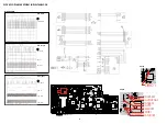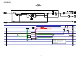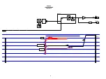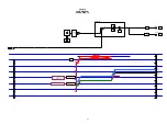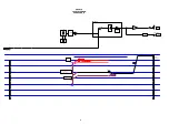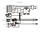
The circuit around CY920 is faulty.
YES
YES
YES
YES
YES
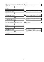
Can the NET1.8V output voltage (1.8 V)
to U1071 (DC-DC Conv.) be confirmed?
Can the NET3.3V output voltage (3.3 V)
to Q1071 (FET-SW) be confirmed?
Can the NET1.2V output voltage (1.2 V)
to U1070 (DC-DC Conv.) be confirmed?
Can the NET2.5V output voltage (2.5 V)
to U1072 (DC-DC Conv.) be confirmed?
Are the versions of the Ethernet SBL and IMG displayed in Version
Check Mode?
Is E_POWER1 (U1018 uCOM 132 pin)
"Hi" ?
Is E_POWER3 (U1018 uCOM 134 pin)
"Hi" ?
Is E_POWER4 (U1018 uCOM 132 pin)
"Hi" ?
Is E_POWER2 (U1018 uCOM 133 pin)
"Hi" ?
The circuit of E_POWER1 between
U1018 and Q1071 are faulty.
The circuit of E_POWER3 between
U1018 and U1071 are faulty.
The circuit of E_POWER4 between
U1018 and U1070 are faulty.
The circuit of E_POWER2 between
U1018 and U1072 are faulty.
The circuit around U1071 (DC-DC.
Conv.) is faulty.
The circuit around Q1071 (FET-SW) is
faulty.
The circuit around U1070(DC-DC.
Conv.) is faulty.
The circuit around U1072 (DC-DC.
Conv.) is faulty.
The Ethernet software is faulty.
NO
NO
NO
NO
NO
NO
NO
NO
NO
YES
YES
YES
YES
84
Содержание SR5010/K1B
Страница 8: ...Personal notes 8 ...
Страница 100: ...POWER DIAGRAM S2 8V 8V MAIN TRANS S1 AMP B MAIN PWR ON VCC DIAGRAM AC CORD 100 ...
Страница 156: ...2 FL DISPLAY FLD GP1261AI FRONT FLT4400 PIN CONNECTION PATTERN DETAIL 156 ...
Страница 157: ...ANODE CONNECTION 157 ...


