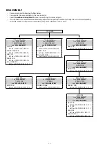
6. MAIN PCB
Proceeding : TOP COVER
→
BACK CHASSIS
→
HDMI PCB
→
VIDEO PCB
→
PREOUT PCB
→
MAIN PCB
(1) Remove the screws.
(2) Remove the screws.
7. SMPS PCB
Proceeding : TOP COVER
→
SMPS PCB
See "EXPLODED VIEW" for instructions on removing the SMPS PCB.
8. TRANS
Proceeding : TOP COVER
→
HDMI PCB
→
TRANS
See "EXPLODED VIEW" for instructions on removing the transformer (TRANS).
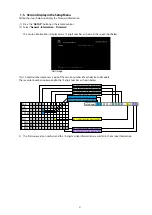
View from the bottom
x3
x8
x2
from CP405
from CP403
CP402
CP401
CP5003
17
Содержание SR5010/K1B
Страница 8: ...Personal notes 8 ...
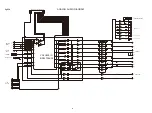
Страница 100: ...POWER DIAGRAM S2 8V 8V MAIN TRANS S1 AMP B MAIN PWR ON VCC DIAGRAM AC CORD 100 ...
Страница 156: ...2 FL DISPLAY FLD GP1261AI FRONT FLT4400 PIN CONNECTION PATTERN DETAIL 156 ...
Страница 157: ...ANODE CONNECTION 157 ...


