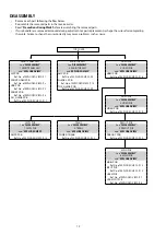
1. FRONT PANEL ASSY
Proceeding : TOP COVER
→
FRONT PANEL ASSY
(1) Remove the screws.
(2) Remove the screws. Remove the CORD HOLDERs and the connector wires. Remove the FFC.
2. RADIATOR ASSY
Proceeding : TOP COVER
→
FRONT PANEL ASSY
→
RADIATOR ASSY
(1) Remove the screws.
(2) Remove the CORD HOLDERs and connector wires.
View from the bottom
x8
FFC
FFC
N1008
CP4400
CORD HOLDER
View from the bottom
Shooting direction: C
Shooting direction: D
x7
CP405
CP403
CP402
CP401
CORD HOLDER
14
Содержание SR5010/K1B
Страница 8: ...Personal notes 8 ...
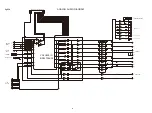
Страница 100: ...POWER DIAGRAM S2 8V 8V MAIN TRANS S1 AMP B MAIN PWR ON VCC DIAGRAM AC CORD 100 ...
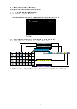
Страница 156: ...2 FL DISPLAY FLD GP1261AI FRONT FLT4400 PIN CONNECTION PATTERN DETAIL 156 ...
Страница 157: ...ANODE CONNECTION 157 ...


