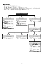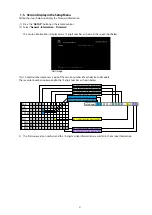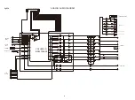
Explanatory Photos for DISASSEMBLY
• For the shooting direction of each photos used in this manual, see the photo below.
•
A, B, C and D
in the photo below indicate the
shooting directions
of photos.
• The photographs with no shooting direction indicated were taken from the top of the unit.
• Photos of SR5010 N1SG are used in this manual.
The viewpoint of each photograph
(Shooting direction : X) [View from the top]
Front side
Shooting
direction: D
Shooting
direction: C
↑
Shooting direction: A
↑
↓
Shooting direction: B
↓
13
Содержание SR5010/K1B
Страница 8: ...Personal notes 8 ...
Страница 100: ...POWER DIAGRAM S2 8V 8V MAIN TRANS S1 AMP B MAIN PWR ON VCC DIAGRAM AC CORD 100 ...
Страница 156: ...2 FL DISPLAY FLD GP1261AI FRONT FLT4400 PIN CONNECTION PATTERN DETAIL 156 ...
Страница 157: ...ANODE CONNECTION 157 ...


