50960025/CP0514
60
PRINTED IN U.S.A.
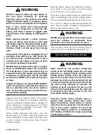
To ensure proper load carrying capability, original
equipment tires comply with the specifications pub-
lished in the
Tire and Rim Association Yearbook
.
Replacement tires MUST meet the same specifica-
tions. When replacing tires, be sure all tires are of the
same type, quality and load rating, and the same size as
the original equipment. When removing tires, follow
industry safety practices. Deflate completely prior to
removal. After assembly of the tire on the rim, use a
safety cage or restraining device while inflating.
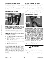
CHECKING WHEEL NUT TORQUE
On new machines, or any time a wheel has been
removed, re-torque until 450 ft.-lbs. (610 Nm) is main-
tained.
CHECKING INSTRUMENTS OPERATION
Allow the engine to warm up for 1-2 minutes or 2-4
minutes in below freezing temperatures before begin-
ning operation. Indicator lamps should be OFF and
gauges should register normal readings. Tilt the frame
from side to side with the frame leveling control and
note the angle indicator movement.
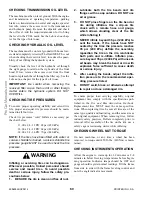
CHECKING TRANSMISSION OIL LEVEL
The machine must be on level ground. With the engine
and transmission at operating temperature, parking
brake on, transmission in neutral and engine speed at
low idle, remove the access cover to the transmission
and hydraulic pump. Remove the dipstick and check
the oil level. Add the required amount of oil to bring
the level to the FULL mark. See the
Lubrication
chap-
ter for the type of oil to use.
CHECKING HYDRAULIC OIL LEVEL
The machine must be on level ground with boom low-
ered and completely retracted. The fluid MUST be cool
when checking the reservoir level, to reduce the possi-
bility of overfilling the hydraulic system.
Visually check the level of the hydraulic oil through
the sight gauge located on the right side of the front
hood. If low, remove the access cover from the front
hood to replenish the oil through the filler cap. See the
Lubrication
chapter for the type of oil to use.
IMPORTANT:
Be careful when removing the
reservoir filler cap so that no dirt or other foreign
matter enters the hydraulic system. DO NOT
OVERFILL.
CHECKING TIRE PRESSURES
To ensure proper operating stability and extend tire
life, proper and equal tire pressure should be main-
tained in all four tires.
Check tire pressures “cold.” Inflate as necessary per
the chart below:
13.00 x 24 - 12 PR: 65 psi (450 kPa)
14.00 x 24 - 12 PR: 62 psi (430 kPa)
14.00 x 24 - 16 PR: 70 psi (480 kPa)
NOTE:
If the tires have been filled with water or
calcium chloride for ballast, a calcium chloride tire
pressure gauge MUST be used to check the tire
pressure.
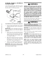
WARNING
Inflating or servicing tires can be dangerous.
Whenever possible, trained personnel should
service and mount tires. To avoid possible
death or serious injury, follow the safety pre-
cautions below:
1.
BE SURE the rim is clean and free of rust.
2.
Lubricate both the tire beads and rim
flanges with a soap solution. DO NOT use
oil or grease.
3.
DO NOT place fingers on the tire bead or
rim during inflation. Use a clip-on tire
chuck with a remote hose and gauge,
which allows standing clear of the tire
while inflating it.
4. NEVER inflate beyond 35 psi (240 kPa) to
seat the beads. If the beads have NOT
seated by the time the pressure reaches
35 psi (240 kPa), deflate the assembly,
reposition the tire on the rim, relubricate
both parts and re-inflate. Inflation pres-
sure beyond 35 psi (240 kPa) with unseat-
ed beads may break the bead or rim with
explosive force sufficient to cause death
or serious injury.
5.
After seating the beads, adjust the infla-
tion pressure to the recommended oper-
ating pressure listed.
6.
DO NOT weld, braze, or otherwise attempt
to repair and use a damaged rim.
Содержание MT10044XT
Страница 12: ...50960025 CP0514 8 PRINTED IN U S A INTENTIONALLY BLANK To be removed as Dealer s file copy ProCarManuals com...
Страница 25: ...PRINTED IN U S A 21 50960025 CP0514 SAFETY 808034 808035 808033 808032 808036 808031 51200535 ProCarManuals com...
Страница 85: ...PRINTED IN U S A 81 50960025 CP0514 Date Hours Service Procedure MAINTENANCE LOG ProCarManuals com...
Страница 86: ...50960025 CP0514 82 PRINTED IN U S A Date Hours Service Procedure MAINTENANCE LOG ProCarManuals com...
Страница 87: ...PRINTED IN U S A 83 50960025 CP0514 Date Hours Service Procedure MAINTENANCE LOG ProCarManuals com...
Страница 91: ...PRINTED IN U S A 87 50960025 CP0913 Hydraulic Schematic for Two Joystick Control without PWP ProCarManuals com...
Страница 92: ...50960025 CP0913 88 PRINTED IN U S A Hydraulic Schematic for Two Joystick Control with PWP ProCarManuals com...
Страница 93: ...PRINTED IN U S A 89 50960025 CP0913 Hydraulic Schematic for Tri Function Joystick without PWP ProCarManuals com...
Страница 94: ...50960025 CP0913 90 PRINTED IN U S A Hydraulic Schematic for Tri Function Joystick with PWP ProCarManuals com...
Страница 95: ...PRINTED IN U S A 91 50960025 CP0913 Electrical Schematic with Radio Remote ProCarManuals com...
Страница 96: ...50960025 CP0913 92 PRINTED IN U S A Electrical Schematic without Radio Remote ProCarManuals com...
Страница 97: ...PRINTED IN U S A 93 50960025 CP0514 INTENTIONALLY BLANK ProCarManuals com...
Страница 108: ...50960025 CP0514 104 PRINTED IN U S A Load Zone Charts MT10055XT Work Platform Decal 50380043 ProCarManuals com...
Страница 114: ...50960025CP0514 2014 Manitou Americas Inc PRINTED IN U S A All Rights Reserved ProCarManuals com...


