50960025/CP0514
40
PRINTED IN U.S.A.
Engine Coolant Temperature
There are two coolant temperature protection features:
High Coolant Temperature WARNING, and High
Coolant Temperature SHUTDOWN.
At the High Coolant Temperature WARNING set-
point, the warning lamp in the engine override switch
and the amber lamp in the exhaust filter gauge will
flash and a slow engine power derate will begin. But if
the coolant temperature drops below the High Coolant
Temperature WARNING set-point, the power will
increase slowly until the engine is back to full power.
The lamp in the switch and exhaust filter gauge will
continue to flash until the power has returned to normal
even if the fault condition has been corrected and the
recovery is in process.
At the High Coolant Temperature SHUTDOWN set-
point, the lamp in the engine override switch and the
amber lamp in the exhaust filter gauge will light conti-
nously, and a fast engine power derate will begin. If the
coolant temperature does not drop below the SHUT-
DOWN set-point within 30 seconds, the engine will
shut down. However, if the coolant temperature drops
below the High Coolant Temperature SHUTDOWN
set-point within 30 seconds, then the power derate
speed will revert to the High Coolant Temperature
WARNING speed of reaction.
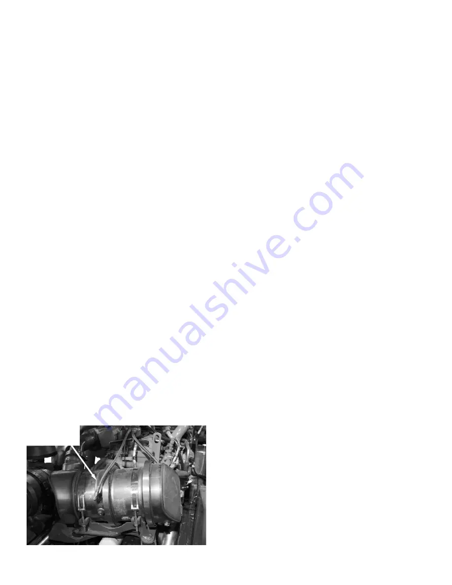
EXHAUST FILTER CLEANING SYSTEM
The engine is equipped with an exhaust filter in place
of a muffler. This filter is located to the front of the
engine under the engine cover. This exhaust filter
reduces carbon monoxide, hydrocarbons, and particu-
late matter from the exhaust stream. Trapped particles
are eventually oxidized through a process known as
regeneration or exhaust filter cleaning.
Under normal machine operation and with the system
in AUTO mode, the exhaust filter requires minimal
operator interaction.
To avoid unnecessary buildup of diesel particles or
soot in the exhaust filter system;
1.
Utilize the Automatic (AUTO) Exhaust Filter
Cleaning mode.
2.
Avoid unnecessary idling.
3.
Use the proper engine oil. See
Lubrication
chap-
ter of this manual or the engine maual for proper
engine oil specifications.
4.
Use only ultra low sulfur diesel (ULSD) fuel. See
Lubrication
chapter of this maual or the engine
manual for fuel requirements.
Even with proper maintenance, ash and soot will build
up in the exhaust filter after several thousand hours of
operation and require service. This service will need to
be performed by a authorized Manitou Americas deal-
er.
Automatic (AUTO) Exhaust Filter Cleaning
Operating the engine in AUTO Mode allows the ECU
to perform intelligent exhaust cleaning as required.
The Exhaust Filter Cleaning Indicator will illuminate
when the system is actively performing an exhaust fil-
ter cleaning. When the exhaust filter cleaning process
has completed its cycle, the cleaning indicator will turn
off.
The machine can be operated as normal during the auto
exhaust filter cleaning process unless the operator
determines the machine is not in a safe location for
high exhaust temperatures and disables the auto clean-
ing process.
To enable the auto exhaust filter cleaning mode, the
exhaust filter cleaning rocker switch should be in the
center position.
IMPORTANT:
It is recommended that the exhaust
filter cleaning be in the Auto mode at all times.
Auto mode should only be disabled when the
machine is not in a safe location during the
exhaust filter cleaning process.
If the machine is not able to be moved to a safe loca-
tion, the operator should temporarily disable auto
exhaust filter cleaning. If the machine is located in a
safe location, the auto mode should always be enabled.
Manual/Parked Exhaust Filter Cleaning
Manual/Parked exhaust filter cleaning is initiated by
the operator. This process allows the system to clean
the exhaust filter when the operator previously needed
to disable the auto exhaust cleaning process because of
Engine Exhaust
Filter
Содержание MT10044XT
Страница 12: ...50960025 CP0514 8 PRINTED IN U S A INTENTIONALLY BLANK To be removed as Dealer s file copy ProCarManuals com...
Страница 25: ...PRINTED IN U S A 21 50960025 CP0514 SAFETY 808034 808035 808033 808032 808036 808031 51200535 ProCarManuals com...
Страница 85: ...PRINTED IN U S A 81 50960025 CP0514 Date Hours Service Procedure MAINTENANCE LOG ProCarManuals com...
Страница 86: ...50960025 CP0514 82 PRINTED IN U S A Date Hours Service Procedure MAINTENANCE LOG ProCarManuals com...
Страница 87: ...PRINTED IN U S A 83 50960025 CP0514 Date Hours Service Procedure MAINTENANCE LOG ProCarManuals com...
Страница 91: ...PRINTED IN U S A 87 50960025 CP0913 Hydraulic Schematic for Two Joystick Control without PWP ProCarManuals com...
Страница 92: ...50960025 CP0913 88 PRINTED IN U S A Hydraulic Schematic for Two Joystick Control with PWP ProCarManuals com...
Страница 93: ...PRINTED IN U S A 89 50960025 CP0913 Hydraulic Schematic for Tri Function Joystick without PWP ProCarManuals com...
Страница 94: ...50960025 CP0913 90 PRINTED IN U S A Hydraulic Schematic for Tri Function Joystick with PWP ProCarManuals com...
Страница 95: ...PRINTED IN U S A 91 50960025 CP0913 Electrical Schematic with Radio Remote ProCarManuals com...
Страница 96: ...50960025 CP0913 92 PRINTED IN U S A Electrical Schematic without Radio Remote ProCarManuals com...
Страница 97: ...PRINTED IN U S A 93 50960025 CP0514 INTENTIONALLY BLANK ProCarManuals com...
Страница 108: ...50960025 CP0514 104 PRINTED IN U S A Load Zone Charts MT10055XT Work Platform Decal 50380043 ProCarManuals com...
Страница 114: ...50960025CP0514 2014 Manitou Americas Inc PRINTED IN U S A All Rights Reserved ProCarManuals com...


