background image

2-45

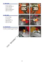
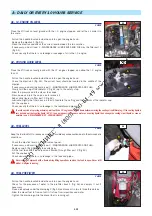
4 - QUICK-RELEASE COUPLER ON ATTACHMENT CIRCUIT

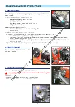
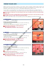
5 - SINGLE SIDE-SHIFT CARRIAGE (TSDL)

The single side-shift carriage (TSDL) is only compatible with the following attachments:
 • floating fork carriage (TFF)
 • tilting fork carriage (PFB)
 • loading bucket (CBR)
 • concrete bucket (BB, BBG)
 • spout bucket (GL)
 • crane jib and crane jib with winch (P, PT, PO, PC)
 • winch (H)
 • fixed platform, swivelling platform, roofer’s platform
It is prohibited to use any other attachments on the TSDL.

If it is being used with a loading bucket (CBR), the single side-shift carriage MUST be centred and no
side-shift operations performed.

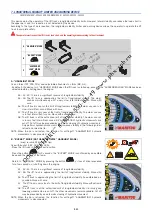
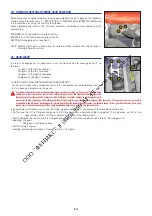
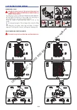
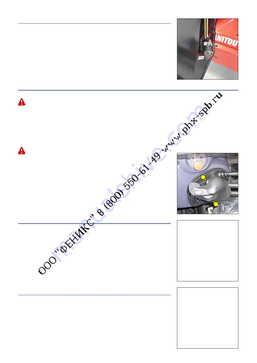
WITH JIB HEAD ELECTROVALVE

- Button 1 controls the single side-shift carriage.
- With button 2 held down, button 1 will control the attachment.

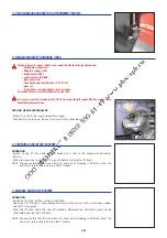
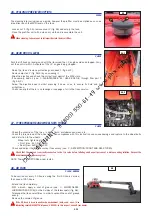
6 - FINTRONIC ANTI-START SYSTEM

OPERATION

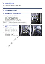
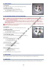
- Switch on the lift truck and set the black key A next to the antenna B (maximum 

80 mm).

- Wait a few seconds for red LED C to go out before star ting the lift truck.
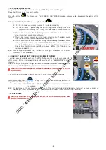
NOTE: You can restar t the lift truck within 20 seconds of stopping it: after this time, the 

anti-star t system reacts and red LED C flashes.

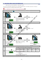
7 - MODCLE ANTI-START SYSTEM

OPERATION

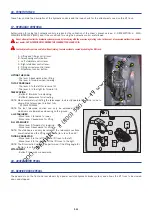
- Switch on lift truck ignition, red led 1 will flash.
- Apply key 2 to its base 3, and withdraw the moment the system emits a continuous beep, 

and led 1 turns green.

- Star t the lift truck within the next 20 seconds; other wise the anti-theft system will be 

reactivated and red led 1 will flash.

NOTE: You can restar t the lift truck within 20 seconds of stopping it: after this time, the 

anti-star t system reacts and red led C flashes.

2

1

Содержание MT 1058 R PRIVILEGE

Страница 1: ......

Страница 2: ...plement 647065 AU 02 07 2007 25 01 2008 11 06 2008 15 01 2009 30 06 2010 18 10 2010 1ST DATE OF ISSUE UP DATING 1 3 1 5 1 10 1 14 1 20 1 26 2 6 2 10 2 13 2 14 2 19 2 21 2 26 2 29 2 38 2 39 3 3 3 11 3...

Страница 3: ......

Страница 4: ...1 1 1 OPERATING AND SAFETY INSTRUCTIONS...

Страница 5: ...1 2...

Страница 6: ...ENTRE OF GRAVITY C LONGITUDINAL STABILITY LIMITER AND WARNING DEVICE D TRANSVERSE ATTITUDE OF THE LIFT TRUCK E TAKING UP A LOAD ON THE GROUND F TAKING UP AND LAYING A HIGH LOAD ON TYRES G TAKING UP AN...

Страница 7: ...define the lift truck s signalling and lighting equipment Contact your dealer Take into account climatic and atmospheric conditions of the site of utilisation Protection against frost see 3 MAINTENANC...

Страница 8: ...l must always be in good condition and kept in the place provided on the lift truck and in the language used by the operator The operator s manual and any plates or stickers which are no longer legibl...

Страница 9: ...shment with respect to the use of lift trucks and must be carried permanently by the operator The operator is not competent to authorise the driving of the lift truck by another person C MAINTENANCE T...

Страница 10: ...uck is used The pictogram posted at the operator station reminds you that Left hand column It is forbidden to lift people with any kind of attachment using a non PLATFORM fitted lift truck Right hand...

Страница 11: ...andle s provided for this purpose Do not jump out of the seat to get down Always pay attention when using the lift truck Do not listen to the radio or music using headphones or earphones Never operate...

Страница 12: ...risk Regularly check the distance between the load or the attachment and the structure and readjust this if necessary If possible use the lift truck at an oil temperature as close as possible to ambie...

Страница 13: ...drawn to the risks involved in using the lift truck in particular Risk of losing control Risk of losing lateral and frontal stability of the lift truck The operator must remain in control of the lift...

Страница 14: ...his cab even for a moment place the forks or attachment on the ground and place the forward reverse selector in neutral Make sure that the lift truck is not stopped in any position that will interfere...

Страница 15: ...fitted with them Select the steering mode HIGHWAY TRAFFIC as model of lift truck see 2 DESCRIPTION INSTRUMENTS AND CONTROLS Retract entirely the jib and put the attachment at 300 mm from the ground P...

Страница 16: ...bligations OPERATING THE LIFT TRUCK WITH A TRAILER For using a trailer observe the regulations in force in your country maximum travel speed braking maximum weight of trailer etc Do not forget to conn...

Страница 17: ...of gravity before any movement fig B2 and set it in the longitudinal axis of the lift truck It is forbidden to move a load heavier than the effective capacity defined on the lift truck load chart For...

Страница 18: ...be between the two lines see 2 DESCRIPTION INSTRUMENTS AND CONTROLS In this position the two front wheels must be off the ground E TAKING UP A LOAD ON THE GROUND Approach the lift truck perpendicular...

Страница 19: ...b Stop the forks in front of the load by alternately extending and retracting the jib 1 or if necessary moving the lift truck forward 2 fig F2 Set the forward reverse selector to neutral Slightly lift...

Страница 20: ...D WARNING DEVICE If necessary move the lift truck 3 forward fig F7 driving very slowly and carefully Place the load in a horizontal position and lay it down on the pile by lowering and retracting the...

Страница 21: ...me SETTING THE STABILIZERS WITH THE JIB UP UNLADEN AND LADEN This operation must be exceptional and performed with great care Raise the jib and retract the telescopes completely Set the lift truck in...

Страница 22: ...E If it is overloaded set the load down in the place from where it was taken If possible lower the load without moving the lift truck Raise the jib 1 to release the load retract 2 and lower the jib 3...

Страница 23: ...ive and stop the lift truck gently and smoothly to minimise swinging of the load Carry the load a few centimetres above the ground max 30 cm the shortest possible jib length Do not exceed the offset i...

Страница 24: ...out Do not pile these materials to the point where it is necessary to step over them D USING THE PLATFORM However experienced they may be operators must acquaint themselves with the emplacement and o...

Страница 25: ...obably spray 7 Near gale 28 33 50 61 13 9 17 1 Whole trees sway it is difficult to walk against the wind Sea heaps up and white foam blown in streaks along the direction of the wind 8 Gale 34 40 62 74...

Страница 26: ...by removing the key button from the transmitter or locking it in an inaccessible place The user must ensure that the instruction manual is accessible at all times and that operators have read and unde...

Страница 27: ...mes of the individuals or companies having performed them the type of operation and its frequency if applicable The part numbers of any lift truck items replaced shall also be indicated LUBRICANT AND...

Страница 28: ...ol unit disconnect this before starting to weld to avoid the risk of causing irreparable damage to electronic components WASHING THE LIFT TRUCK Clean the lift truck or at least the area concerned befo...

Страница 29: ...e protective product to the engine oil Run the I C engine for a short time so that the oil and cooling liquid circulate inside Disconnect the battery and store it in a safe place away from the cold af...

Страница 30: ...ENANCE D EVERY 500 HOURS SERVICE Refit and set the tension in the drive belts see 3 MAINTENANCE C EVERY 250 HOURS SERVICE Turn the I C engine using the starter to allow the oil pressure to rise Reconn...

Страница 31: ...1 28...

Страница 32: ...2 1 2 DESCRIPTION...

Страница 33: ...2 2...

Страница 34: ...TERISTICS MT 1436 R PRIVILEGE 2 8 CHARACTERISTICS MT 1840 R PRIVILEGE 2 10 FRONT AND REAR TIRES 2 12 DIMENSIONS AND LOAD CHART MT 1436 R PRIVILEGE 2 14 DIMENSIONS AND LOAD CHART MT 1840 R PRIVILEGE 2...

Страница 35: ...que cette machine Declares that this machine 7 Est conforme aux directives suivantes et leurs transpositions en droit national Complies with the following directives and their transpositions into nat...

Страница 36: ...DV 3DUHL NLD NDG LV UHQJLQ V WLWLQND WROLDX QXURG WDV GLUHNW YDV LU QDFLRQDOLQLXV WHLV V DNWXV SHUNHOWDV M QXRVWDWDV 9 SULHGDV G O PD LQ 6HUWLILNDWR 1U 3DVNHOEWRML VWDLJD VXGHULQWXV VWDQGDUWXV QDXGRMD...

Страница 37: ...de remolque Pression des pneumatiques Bar Tyre pressure Bar Pressione per pneumatici Bar Presion de los neum ticos Bar kW daN Avant Front Anteriore Adelante Arri re Rear Posteriore Trasero kg kg daN A...

Страница 38: ...LATE MANUFACTURER OF THE ATTACHMENT FIG H Model Serial Nr Year of manufacture N 207701 MODELE N dans la s rie Ann e fabrication Masse vide C d G Tablier Cap Nominale Pression de service AVERTISSEMENT...

Страница 39: ...24 162A8 TUBELESS Pressure bar 4 1 Rear tyres MICHELIN Size 400 80 24 162A8 TUBELESS Pressure bar 4 1 ELECTRIC CIRCUIT Battery according to installation 12 V 110 Ah 750 A EN 12 V 180 Ah 1000 A EN Alt...

Страница 40: ...lug of the forks mm 500 Standard lifting height mm 13520 Lift truck weight without attachment kg 9400 Lift truck weight with standard attachment Unladen kg 9770 At rated load kg 13770 Weight per axle...

Страница 41: ...400 80 24 162A8 TUBELESS Pressure bar 5 Rear tyres MICHELIN Size 400 80 24 162A8 TUBELESS Pressure bar 5 ELECTRIC CIRCUIT Battery according to installation 12 V 110 Ah 750 A EN 12 V 180 Ah 1000 A EN...

Страница 42: ...ug of the forks mm 500 Standard lifting height mm 17500 Lift truck weight without attachment kg 11010 Lift truck weight with standard attachment Unladen kg 11380 At rated load kg 15380 Weight per axle...

Страница 43: ...P 440 80 24 T37 158B TUBELESS 4 2 600 2150 2750 6050 4 5 1250 6 84 1 89 180 650 2650 8 69 2 40 305 1105 3050 8 97 2 50 340 1220 6450 12 97 3 58 498 1803 GALAXY 15 5 25 16PR GIRAFFE L2 4 6 600 2150 275...

Страница 44: ...2 13...

Страница 45: ...960 G mm 378 G1 mm 361 G2 mm 374 G3 mm 349 H 9 H1 9 I mm 1152 J mm 892 K mm 1040 L mm 50 N mm 1849 O mm 125 P2 33 P3 43 R mm 3779 S mm 8610 T mm 4183 U1 mm 2446 U2 mm 2634 V mm 5468 V1 mm 1285 V2 mm 3...

Страница 46: ...42 7 40 5 80 1 80 4 65 8 65 6 50 5 25 950KG 1200KG 1600KG 2000KG 2500KG 3000KG 3600KG N 261391 SUIVANT NORME EN 1459 annexe B MT 1436 60 50 62 14 13 12 11 10 9 8 7 6 5 4 3 2 1 0 1 40 30 20 10 0 6 1 0...

Страница 47: ...1960 G mm 437 G1 mm 420 G2 mm 433 G3 mm 302 H 9 H1 9 I mm 1160 J mm 892 K mm 1040 L mm 50 N mm 1908 O mm 125 P2 37 P3 34 R mm 3779 S mm 8780 T mm 4307 U1 mm 2505 U2 mm 2693 V mm 5592 V1 mm 1285 V2 mm...

Страница 48: ...0 9 10 700KG 900KG 1200KG 1600KG 2000KG 2500KG 3000KG 4000KG MT 1840 60 50 70 76 75 40 30 20 10 0 1 3 N 261548 MT 1840 SUIVANT NORME EN 1459 annexe B 60 50 40 30 20 10 0 6 60 8 14 13 12 11 10 9 8 7 6...

Страница 49: ...2 18 INSTRUMENTS AND CONTROLS 26 26 1 2 3 4 6 7 14 15 17 17 17 17 18 19 20 23 24 24 24 24 24 25 25 25 27 28 29 30 5 9 13 11 8 12 2 34 8 31 10 16 21 22 36 32 33 35...

Страница 50: ...LES 17 HYDRAULIC CONTROLS 18 ACCELERATOR PEDAL 19 SERVICE BRAKE PEDAL 20 FORWARD NEUTRAL REVERSE GEAR SELECTION 21 GEAR LEVER 22 STEERING SELECTION 23 HEATER CONTROL 23 AIR CONDITIONING CONTROLS AIR C...

Страница 51: ...used if the seat belt is defective fixing locking cuts tears etc Repair or replace the seat belt immediately 3 IGNITION SWITCH The key switch has five positions P Ignition off parking position O Ignit...

Страница 52: ...released the system detects the operator s absence and immediately activates the parking brake which may cause a sudden stop for the lift truck 6B INSTRUMENT CONTROL PANEL A REV COUNTER B FUEL LEVEL W...

Страница 53: ...RESSURE LAMP If the lamp comes on when the lift truck is running stop the I C engine immediately and look for the cause see oil level in I C engine crankcase BRAKING OIL LEVEL LAMP If the lamp comes o...

Страница 54: ...wwithbuttonAforthebackuphydrauliccontrol XX i appears on the help screen Hold button A in the same position for 2 seconds to confirm the required hydraulic flow Press the button or actuate button A or...

Страница 55: ...e configured using the ADMIN code on the configuration screen see 2 DESCRIPTION 6D SCREEN DISPLAY CONFIGURATION SCREEN 4 ADMIN 4 8 HAND OPERATED PARKING BRAKE The manual parking brake can be configure...

Страница 56: ...cates that the attachment circuit is in continuous mode The adjustable hydraulic flow with button A for the backup hydraulic control appears XX i i on the help screen Hold button A in the same positio...

Страница 57: ...HAZARD WARNING LIGHTS This switch enables the L H and R H Indicators to be switched on simultaneously with the ignition off NEUTRALIZING THE HYDRAULIC CONTROLS When driving on the road it is highly r...

Страница 58: ...creen 4 Jib lifting angle in degrees Lifting angle sensor fault contact your dealer 5 Blank screen Maintenance key default code with 2 characters to be reported to the dealer if in doubt consult your...

Страница 59: ...uration for that time e g if the operator wants to lower the stabilizers first he must retract and or lower the jib when this screen appears it makes a beeping sound X SELECTION SCREEN These selection...

Страница 60: ...DIGICODE 4 3 BYPASS OK NOK unlocking of operating faults allowed or not allowed BYPASS OK NOK change of state BYPASS COUNT XX time allowed in minutes1 5 10 15 50 4 4 RST HOURS OK NOK reset daily hour...

Страница 61: ...owing order retract and raise the jib B SOUND ALARM This allows you to switch off the sound alarm when using the lift truck with loading and earth moving buckets When it is switched off the red warnin...

Страница 62: ...is at the authorized limit of longitudinal stability The alarm sounds is in very fast intermittent sound All AGGRAVATING hydraulic movements are cut off Cut off may be preceded by automatic slowing of...

Страница 63: ...der retract and raise the jib NOTE When the jib is retracted the function for cutting off AGGRAVATING hydraulic movements is disconnected D DISABLING AGGRAVATING HYDRAULIC MOVEMENT CUT OFF In certain...

Страница 64: ...dscreen wiper and windscreen washer 10A F14 10A MAX OPTION F15 10A MAX OPTION F16 15A MAX OPTION F17 15A MAX OPTION F18 10A MAX OPTION F19 7 5A MAX OPTION F20 15A MAX Window regulator 15A F21 3A MAX O...

Страница 65: ...MAX Electronics box MP1 40A F5 80A MAX Preheating I C engine 80A F6 80A MAX Alternator 80A 2nd ASSEMBLY FROM MACHINE N 586523 K20 Pre heating relay K27 OPTION Diesel decongealant relay MINIFUSE F51 TO...

Страница 66: ...and the rear lights are on F The main beam headlights and the rear lights are on G Headlight signal Pressing the switch sounds the horn NOTE The positions D E F G can be carried out without the igniti...

Страница 67: ...e lever A to the left for reverse tilt The lever A to the right for forward tilt TELESCOPING Button B forwards for extending Button B backwards for retracting NOTE When completely retracting the teles...

Страница 68: ...ar ratio should be made carefully according to the nature of the work being carried out A poor choice may result in the extremely rapid rise of the transmission oil temperature through excessive slipp...

Страница 69: ...Front and rear drive wheels in the same direction crab steering CONTROL FOR ALIGNMENT OF THE WHEELS Shift the steering selection lever B into position B2 short steering lock Turn the steering wheel an...

Страница 70: ...examined by your dealer see 3 MAINTENANCE F EVERY 2000 HOURS OF SERVICE Never try to repair any anomalies yourself A FAN CONTROL This 3 speed control allows the air to be ventilated through the air ve...

Страница 71: ...OPEN LEVER 28 DOOR CLOSE HANDLE 29 WINDOW REGULATOR SWITCH 30 SIDE STORAGE SPACE 31 ROOF LIGHT 32 HANDLE FOR REAR WINDOW OPENING EMERGENCY EXIT Use the rear window as an emergency exit if it is impos...

Страница 72: ...ont main beam H Right front sidelight 37 REAR LIGHTS A Left rear indicator B Left rear stoplight C Left tail light D Left rear fog light E Right rear reverse light F Right tail light G Right rear stop...

Страница 73: ...LER To couple the trailer position the lift truck as close as possible to the trailer ring Switch off the I C engine Remove the clip 1 lift the trailer pin 2 and place or remove the trailer ring Be ca...

Страница 74: ...2 43...

Страница 75: ...with a cable that conforms to the installation standards in force and contains a protective earth conductor Contains an appropriate sectioning system Incorporate an appropriate safety system against s...

Страница 76: ...With button 2 held down button 1 will control the attachment 6 FINTRONIC ANTI START SYSTEM OPERATION Switch on the lift truck and set the black key A next to the antenna B maximum 80 mm Wait a few sec...

Страница 77: ...1436 3000KG MAXI 3m Mini 1 40m Maxi 0 3m Maxi 8 7 6 5 4 3 2 1 0m 9 10 12 13 14 15 11 10 9 8 7 6 5 4 3 2 1 0 1 30 40 13 35 20 10 0 50 60 70 71 4 900KG 1600KG 1200KG 2000KG 2500KG 3000KG 750KG 0KG 4 70...

Страница 78: ...3 1 3 MAINTENANCE...

Страница 79: ...3 2...

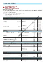
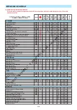
Страница 80: ...TS AND FUEL 3 8 SERVICING SCHEDULE 3 10 A DAILY OR EVERY 10 HOURS SERVICE 3 12 B EVERY 50 HOURS SERVICE 3 16 C EVERY 250 HOURS SERVICE 3 22 D EVERY 500 HOURS SERVICE 3 24 E EVERY 1000 HOURS SERVICE 3...

Страница 81: ...USING ORIGINAL MANITOU PARTS FOR MAINTENANCE OPERATIONS YOU BENEFIT Through its network MANITOU provides the user with EXPERTISE Know how and competence The guarantee of high quality work Original rep...

Страница 82: ...nd parking brake operation 02 Brake fluid level 105 LUBRICATION AND GREASING 106 JIB MANISCOPIC MANIACCESS ASSEMBLY 01 Beam and telescope s 02 Skid 03 Hinges 04 Carriage 05 Forks 107 MAST ASSEMBLY 01...

Страница 83: ...CLEANING PRE FILTER OPTION Part number 226611 FUEL TANK BREATHER Part number 266219 Change 1000 H This periodicity is given for information only see 3 MAINTENANCE SERVICING SCHEDULE for cleaning and c...

Страница 84: ...3 7...

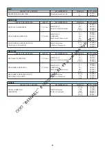
Страница 85: ...e N590 diesel fuel type Auto C0 C1 C2 C3 C4 BS2869 Class A2 ASTM D975 91 Class 2 2DA US DF1 US DF2 US DFA JIS K2204 1992 Grades 1 2 3 and Special Grade 3 TRANSMISSION ORGANS TO BE LUBRICATED CAPACITY...

Страница 86: ...N MANITOU Grease BLACK multi purpose 400 g 1 kg 5 kg 545996 161590 499235 REAR AXLE ORGANS TO BE LUBRICATED CAPACITY RECOMMENDATION PACKAGING PART NUMBER REAR AXLE DIFFERENTIAL 7 2 Liters MANITOU Oil...

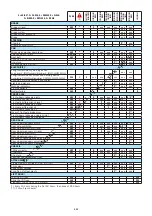
Страница 87: ...ter cartridge 3 25 R R Fuel tank 3 28 N Fuel tank breather 3 28 R Safety dry air filter cartridge 3 28 R I C engine silent blocks C I C engine rates C Valves clearances C C Cooling liquid 3 32 V Radia...

Страница 88: ...ing harness and cables C Lights and signals C Warning indicators C Front headlights 3 35 A Battery failure 3 35 R FRONT AXLE Front wheels reducers pivots 3 20 G G G C Front axle oscillation 3 20 G G G...

Страница 89: ...re is no leakage in the radiator and pipes To avoid any risk of spraying or burning wait until the I C engine has cooled down before removing the cooling circuit filler plug If the cooling liquid is v...

Страница 90: ...n A7 TYRES PRESSURE AND WHEEL NUTS TORQUE CHECK Check the condition of the tyres to detect cuts protuberances wear etc Check the torque load of the wheel nuts Non compliance with this instruction can...

Страница 91: ...ering slows until movement is next cut off Short press on the test button TEST OK First 5 leds lit Screen display TEST OK Press the button to exit test mode TEST NOT OK See stage 4 STAGE 4 The fault w...

Страница 92: ...3 15...

Страница 93: ...ridge seal surfaces with a damp clean lint free cloth and grease with a silicone lubricant MANITOU reference 479292 Check visually the outer condition of the air filter and its mounts Verify the condi...

Страница 94: ...points with grease see 3 MAINTENANCE LUBRICANTS AND FUEL and remove the surplus of grease 1 Lubricators of the universal joint Transmission Front axle 3 lubricators fig B4 1 2 Lubricators of the unive...

Страница 95: ...rs of the jib axle 2 lubricators fig B5 1 2 Lubricators of the carriage axle 2 lubricators fig B5 2 3 Lubricator of the tilt cylinder head axle 1 lubricator fig B5 2 4 Lubricator of the tilt cylinder...

Страница 96: ...asing B7 BRAKE OIL LEVEL CHECK Place the lift truck on level ground Remove protective casing 1 fig B7 1 using the switch key Check tank 2 fig B7 2 The correct level must stand at the MAX level in the...

Страница 97: ...back into place Put the protective grid back into place B10 FRONT AND REAR WHEEL REDUCER PIVOTS GREASE Clean and lubricate the points 1 8 lubricators fig B10 with grease see 3 MAINTENANCE LUBRICANTS A...

Страница 98: ...s fig B13 1 2 Lubricators of the stabilizers cylinders head axle 2 lubricators fig B13 2 3 Lubricators of the stabilizers axles 2 lubricators fig B13 3 B14 SINGLE SIDE SHIFT CARRIAGE TDSL OPTION GREAS...

Страница 99: ...C2 1 Lay down the protective guard 2 fig C2 1 After adjusting the compressor belt you must carry out the adjustment of the alternator belt COMPRESSOR BELT Check the belt for signs of wear and cracks a...

Страница 100: ...t truck on level ground with the I C engine stopped Remove level plug 1 fig C5 The oil should be flush with the edge of the hole If necessary add oil see 3 MAINTENANCE LUBRICANTS AND FUEL by the fille...

Страница 101: ...il filter Stop the I C engine wait a few minutes and check the correct level on the dipstick 6 fig D1 3 between the two level marks Top up the level if necessary Refit access panel 1 fig D1 1 D3 DRY A...

Страница 102: ...p is on Pull on the handle located inside the cab to open the engine hood Carefully clean the outside of the filter and its holder to prevent dust from getting into the system Place a container under...

Страница 103: ...k the assembly then retighten the cover Refit the filling cap Refit the protective casing D7 FRONT AND REAR AXLE DIFFERENTIAL OIL DRAIN Place the lift truck on level ground with the I C engine stopped...

Страница 104: ...3 27...

Страница 105: ...compartment 4 fig E1 3 Unscrew the breather 5 fig E1 4 and replace with a new one see 3 MAINTENANCE FILTERS CARTRIDGES AND BELTS tightening torque 5 2 N m Fill the fuel tank with clean diesel filtere...

Страница 106: ...e new seal before refitting the new oil filter see 3 MAINTENANCE FILTERS AND BELTS on its bracket Tighten the oil filter by hand pressure only and lock the filter in place by a quarter turn FILLING UP...

Страница 107: ...strainer making sure the seal is in the correct position REPLACING THE BRAKE ACCUMULATOR UNIT FILTER Unscrew plug 7 fig E6 5 remove the filter and replace with a new one Refit and tighten plug 7 fig E...

Страница 108: ...uck be used if the seat belt is defective fixing locking cuts tears etc Repair or replace the seat belt immediately E11 FRONT AND REAR WHEELS REDUCERS OIL DRAIN Place the lift truck on level ground wi...

Страница 109: ...it drain entirely while ensuring that the ports do not get clogged Check the condition of the hoses as well as the fastening devices and change the hoses if necessary Rinse the circuit with clean wate...

Страница 110: ...ot open the circuit under any circumstances as this would cause the coolant to be lost The cooling circuit contains a gas which can be dangerous under certain conditions This gas coolant R 134a is col...

Страница 111: ...he I C engine functions correctly for a short time then stops or functions irregularly check for possible leaks in the low pressure circuit If in doubt contact your dealer G2 WHEEL CHANGE In the event...

Страница 112: ...CHANGE Pull on the handle located inside the cab to open the engine hood Bring a floating battery of the same type as the one used for the lift truck and battery cables Connect the floating battery w...

Страница 113: ...r to release the brake disk Allow a minimum clearance of 5 mm between the disk and the brake pads Put the towing device into place Remove the clamps Put the warning lights on NOTE Since there will be...

Страница 114: ...n of the turbo shaft without lubrication when transporting the vehicle LOAD THE LIFT TRUCK Block the wheels of the platform Fix the loading ramps so that you obtain an angle as little as possible to l...

Страница 115: ...rgency stop button the IC engine must stop A visual alarm and a long sound signal are triggered at the same time and the general fault screen appears on the screen display 3 GROUND STABILISERS Place t...

Страница 116: ...4 1 4 OPTIONAL ATTACHMENTS FOR USE WITH THE RANGE...

Страница 117: ...4 2...

Страница 118: ...4 3 TABLE OF CONTENTS INTRODUCTION 4 5 PICKING UP THE ATTACHMENTS 4 6 TECHNICAL SPECIFICATIONS OF ATTACHMENTS 4 8 ATTACHMENT SHIELDS 4 13...

Страница 119: ...4 4...

Страница 120: ...ts approved by MANITOU are to be used on our lift trucks see 4 ADAPTABLE ATTACHMENTS IN OPTION ON THE RANGE TECHNICAL SPECIFICATIONS OF ATTACHMENTS The manufacturer s liability will be denied in case...

Страница 121: ...fig B Bring the carriage under the locking tube of the attachment slightly lift the jib incline the carriage backwards in order to position the attachment fig C Lift the attachment off the ground to...

Страница 122: ...ECTION OF THE ATTACHMENT Take the locking pin and the clip on the bracket fig A and lock the attachment fig D Do not forget to refit the clip Stop the I C engine and keep the ignition on the lift truc...

Страница 123: ...m 1300 mm Weight 370 kg 400 kg FLOATING FORK SIDE SHIFT CARRIAGE Use is prohibited with the optional single side shift carriage TSDL TFF 45 MT 1040 DL TFF 45 MT 1300 DL PART NUMBER 751545 751546 Rated...

Страница 124: ...54407 653747 653748 Rated capacity 4500 kg 4500 kg 4500 kg Width 1260 mm 1670 mm 2000 mm Weight 200 kg 255 kg 300 kg LOAD BACK REST MT 1840 R PRIVILEGE PART NUMBER 727035 572788 572790 Width 1260 mm 1...

Страница 125: ...0 mm Weight 385 kg 410 kg LOADING BUCKET CBR 900 L2250 S2 CBR 1000 L2450 S2 PART NUMBER 653749 654716 Rated capacity 904 l 990 l Width 2250 mm 2450 mm Weight 390 kg 410 kg BUCKET 4X1 Use is prohibited...

Страница 126: ...ADAPTABLE ON FORKS GL 300 S2 GL 400 S2 PART NUMBER 174371 174372 Rated capacity 300 l 725 kg 400 l 969 kg Weight 150 kg 166 kg HYDRAULIC KIT TO OPEN THE SPOUT PART NUMBER 653750 SPOUT BUCKET ADAPTABLE...

Страница 127: ...with a lift truck equipped with an operational hydraulic movement cut out device PT 600 MT S6 PART NUMBER 708538 Rated capacity 600 kg Weight 288 kg 15 15 MULTI DIRECTIONAL CRANE JIB MUST be used wit...

Страница 128: ...an or equal to the width of the bucket PART NUMBER 206734 206732 206730 Width 1375 mm 1500 mm 1650 mm PART NUMBER 235854 206728 206726 Width 1850 mm 1950 mm 2000 mm PART NUMBER 223771 223773 206724 Wi...

Страница 129: ...4 14...

Страница 130: ...5 1 5 SPECIFIC CANADA...

Страница 131: ...5 2...

Страница 132: ...5 3 TABLE OF CONTENTS DIMENSIONS AND LOAD CHART MT 1058 R PRIVILEGE 5 4...

Страница 133: ...000 G mm 437 G1 mm 420 G2 mm 433 G3 mm 302 H 9 H1 9 I mm 1160 J mm 892 K mm 1800 L mm 50 N mm 1908 O mm 150 P2 37 P3 34 R mm 3779 S mm 8820 T mm 4546 U1 mm 2505 U2 mm 2693 V mm 5830 V1 mm 1285 V2 mm 3...

Страница 134: ...58 SUIVANT NORME ASME B56 6 2002 50 60 70 76 MT 1058 0 6m 24in Meter Feet 0 10 20 30 40 2 SUIVANT NORME ASME B56 6 2002 41ft3in N 270153 50 60 62 40 30 20 10 0 7 14 13 12 11 10 9 8 7 6 5 4 3 2 1 0 1 4...

Страница 135: ...5 6...

Страница 136: ...6 1 6 SPECIFIC AUSTRALIA See also the operator s manual supplement 647065 AU...

Страница 137: ...6 2...

Страница 138: ...surface CHARIOT Bar PSI N 272041 5 maxi kg 10 maxi kg kg MT1436 P 0km h 0 6m 50 60 70 72 4 40 30 20 10 0 0 8 13 52 15 13 14 12 11 10 9 8 7 6 5 4 3 2 1 0 1 8 7 6 5 4 3 2 1 0m 9 10 9 52 7 40 4 65 5 80 1...

Страница 139: ...6 4...
Отзывы: