


24
solutions creator
TC 322 - TC328
ITALIANO
ENGLISH
ISTRUZIONI PER L’USO
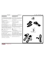
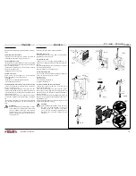
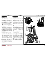
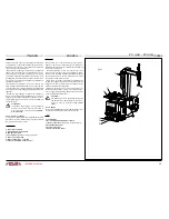
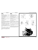
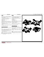
OPERAZIONI DI MONTAGGIO (ved.fig.30 e fig.31)
• Lubrificare i talloni del pneumatico ed appoggiarlo sul
cerchio.
• Portare la torretta in posizione di lavoro.
• Appoggiare il tallone sul bordo della torretta (I) e sotto
la linguetta(fig.31).
• Far ruotare l’autocentrante premendo il pedale (A) aven-
do cura di far entrare il tallone nella gola centrale del cer-
chio, al fine di eliminare snervamenti del tallone stesso.
• (per favorire questa operazione si consiglia di premere
con le mani sul pneumatico).
• Spostare il braccio (per liberare la zona di lavoro).
• Posizionare il cerchio, con il foro per la valvola della ca-
mera d’aria a circa 90° gradi dalla torretta; quindi inserire
la camera d’aria.
• Ripetere le operazioni iniziali (vedi sopra) per fare en-
trare il secondo tallone. Nel caso in cui il tallone fatichi
a scendere dalla torretta è necessario “alzare” (azionare
verso l’alto) il pedale invertitore (A) facendo ruotare l’au-
tocentrante in senso antitorario.
• Spostare il braccio, premere il pedale apertura (C) per
sbloccare il cerchio
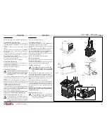
OPERAZIONI DI GONFIAGGIO
INSTRUCTIONS FOR USE
MOUNTING (see fig.30 and fig.31)
• Lubricate the tyre bead and place it on the rim; move
the head to the working position.
• Place the bead on the edge of the head (I) and under
the tongue (fig.31).
• Rotate the chuck by pressing pedal (A) taking care to
make the bead move into the central groove of the rim so
as to eliminate weakening the bead.
• (to help this action it is advisable to press down on the
tyre with the hands).
• Move the adjstable arm (to free the work area).
• Place the rim with the inner tube valve at about 90° to
the head, then insert the inner tube.
• Repeat the initial operation (see above) to locate the
second bead.
• In the case that the bead has difficulty descending from
the head, itis necessary to “raise” (move upwards) the
invertor pedal (A) making the chuck rotate in an anti-
clockwise direction.
• Move the arm and press the open pedal (C) to unlock
the rim.
INFLATION PROCESS
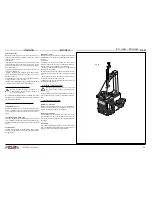
ATTENZIONE !
L’operazione di gonfiaggio è potenzialmente
pericolosa.(Ved. Fig.32).
L’operatore deve adottare tutte le misure ne-
cessarie pergarantire LE CONDIZIONI DI SICU-
REZZA.
DISPOSITIVO DI SICUREZZA PER IL GONFIAGGIO
Al fine di proteggere l’operatore dai potenziali pericoli
derivanti dal gonfiaggio del pneumatico sul piatto del-
l’autocentrante, la macchina é stata dotata di una valvola
limitatrice della pressione di esercizio tarata a 3,5 bar e da
una valvola di massima pressione tarata a 4 bar.
WARNING !
The inflation process is potentially
dangerous.(see fig.32).
The operator must adopt all the measures
necessary in order to guarantee SAFE CONDI-
TIONS.
INFLATION SAFETY DEVICE
The machine is fitted with a pressure limiting valve set at
3.5 bar and a maximum pressure valve set at 4 bar. These
are designed to protect the operator from potential danger
resulting from the inflation of tyres on the chuck plate.
ITALIANO
ENGLISH
COLIBRI BL 512
22
COD. 102731 Rev.0
ISTRUZIONI PER L’USO
OPERAZIONI DI MONTAGGIO
(ved.fig.27 e fig. 25)
»
Lubrificare i talloni del pneumatico ed appoggiarlo sul cerchio;
»
Portare la torretta in posizione di lavoro;
»
Appoggiare il tallone sul bordo della torretta (I) e sotto la linguetta
(fig.27);
»
Far ruotare l’autocentrante premendo il pedale (A) avendo cura di far
entrare il tallone nella gola centrale del cerchio, al fine di eliminare
snervamenti del tallone stesso.
»
(
per favorire questa operazione si consiglia di premere con le mani sul
pneumatico
).
»
Spostare il braccio (per liberare la zona di lavoro)
»
Posizionare il cerchio, con il foro per la valvola della camera d’aria a
circa 90° gradi dalla torretta; quindi inserire la camera d’aria
»
Ripetere le operazioni iniziali (vedi sopra) per fare entrare il secondo
tallone.
Nel caso in cui il tallone fatichi a scendere dalla torretta è
necessario “alzare” (azionare verso l’alto) il pedale invertitore (A) facendo
ruotare l’autocentrante in senso antitorario.
»
Spostare il braccio, premere il pedale apertura (C) per sbloccare il
cerchio
OPERAZIONI DI GONFIAGGIO
ATTENZIONE !
L’operazione di gonfiaggio è potenzialmente pericolosa.
(Ved. Fig.28-29)
L’operatore deve adottare tutte le misure necessarie per
garantire LE CONDIZIONI DI SICUREZZA
DISPOSITIVO DI SICUREZZA PER IL GONFIAGGIO
Al fine di proteggere l’operatore dai potenziali pericoli derivanti dal
gonfiaggio del pneumatico sul piatto dell’autocentrante, la macchina é
stata dotata di una
valvola limitatrice della pressione di esercizio
tarata a 3,5 bar e da una
valvola di massima pressione
tarata a 4 bar.
ATTENZIONE !
Per gonfiare il pneumatico sul piatto dell’autocentrante in
condizioni di “MASSIMA SICUREZZA” si consiglia di
richiedere, installare ed applicare le apposite CINTURE DI
SICUREZZA.
( ved. fig.10 a pag 10 e le pagine 26 e 28)
INSTRUCTIONS FOR USE
MOUNTING
(see fig.27 and fig. 25)
»
Lubricate the tyre bead and place it on the rim; move the head to the
working position.
»
Place the bead on the edge of the head (I) and under the tongue (fig. 27)
»
Rotate the chuck by pressing pedal (A) taking care to make the bead
move into the central groove of the rim so as to eliminate weakening
the bead.
»
(to help this action it is advisable to press down on the tyre with the
hands).
»
Move the adjstable arm (to free the work area)
»
Place the rim with the inner tube valve at about 90° to the head, then
insert the inner tube
»
Repeat the initial operation (see above) to locate the second bead.
»
In the case that the bead has difficulty descending from the head, it
is necessary to “raise” (move upwards) the invertor pedal (A) making
the chuck rotate in an anti clockwise direction.
»
Move the arm and press the open pedal (C) to unlock the rim
INFLATION PROCESS
WARNING !
The inflation process is potentially dangerous.
(see fig. 28/29)
The operator must adopt all the measures necessary in or-
der to guarantee SAFE CONDITIONS
INFLATION SAFETY DEVICE
The machine is fitted with a
pressure limiting valve
set at 3.5 bar and
a
maximum pressure valve
set at 4 bar. These are designed to protect
the operator from potential danger resulting from the inflation of tyres on the
chuck plate.
WARNING !
To inflate tyres on the chuck plate in conditions of “MAXIMUM
SAFETY” it is advisable to order, install and use the special
SAFETY BELTS
(see fig.10 on pg 10 and pgs 26 and 28)
27
28
29
fig.32
fig.31
Quando si usa l’aria compressa, si consiglia
l’utilizzo di idonei Dispositivi di protezione
(cuffie o tappi).
When using compressed air, we recommend to
wear suitable safety devices (headsets or ear
plugs).
- TC325
Содержание TC 325
Страница 2: ......


