12
13
14
15
Repairing coolant pump with high-temperature
and low-temperature parts
47
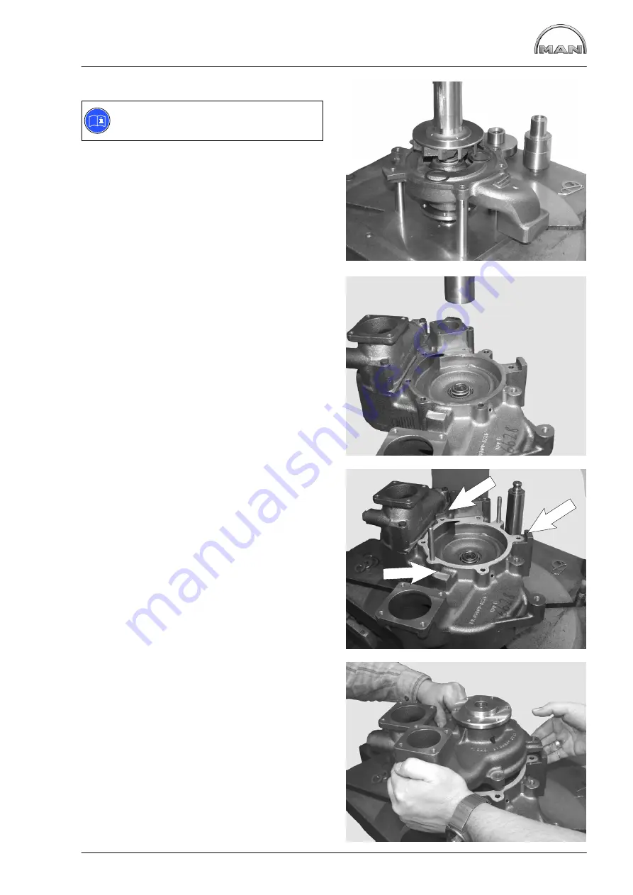
Fig. 12
Note:
Brace the bearing shaft.
Slowly press impeller on to bearing shaft to ensure
correct gap (0,5
+0,4
).
Fig. 13
Press in new mechanical seal (pos. 8) with press-
fitting sleeve (special tool) until it stops.
Observe installation note for seal on page 50.
Fig. 14
Lay coolant pump gasket on pump housing.
Fig. 15
Carefully fit low-temperature suction part to high-
temperature pump housing.
To make assembly easier insert 2 pins in opposite
sides of HT part (see Fig. 14)
Do not use force (hammer etc.) and note the 3
centring features (see arrows in Fig. 14).
Screw in bolt (Fig. 1, item 5).
Bolt LT and HT parts together with 2 bolts and nuts
on opposite sides (Fig. 1, item 4).
Содержание D 2842 LE 620
Страница 1: ......
Страница 2: ......
Страница 20: ...Engine views D 2842 LE 620 18 7 1 2 4 3 5 6 7 1 2 4 11 9 10 8...
Страница 136: ...134...
Страница 137: ...135 Service Data...
Страница 163: ...161 Special tools...
Страница 164: ...Special tools 162 1 2 3 4 5 6 7 8 9 10 11 11 1 11 2 12 12 1 12 2 13 14...
Страница 166: ...Special tools 164 15 1 15 2 15 3 15 4 15 5 1 2 7 15 6 3 4 5 6 15 7...
Страница 168: ...Special tools 166 16 16 1 16 2 16 3 16 6 17 16 4 16 5 16 7 18 19 20 1 20 2 21 22 23 24 25 26 27 28...
Страница 170: ...Special tools 168 3 1 4 29 5 6 2 29 30 31 32 33 34 35...
Страница 172: ...Special tools 170 36 37 38 39 42 40 41 44 2 44 1 44 43 1 43 2 43 3 43 45 46...
Страница 178: ...176...
Страница 179: ......
Страница 180: ......


