5
6
7
8
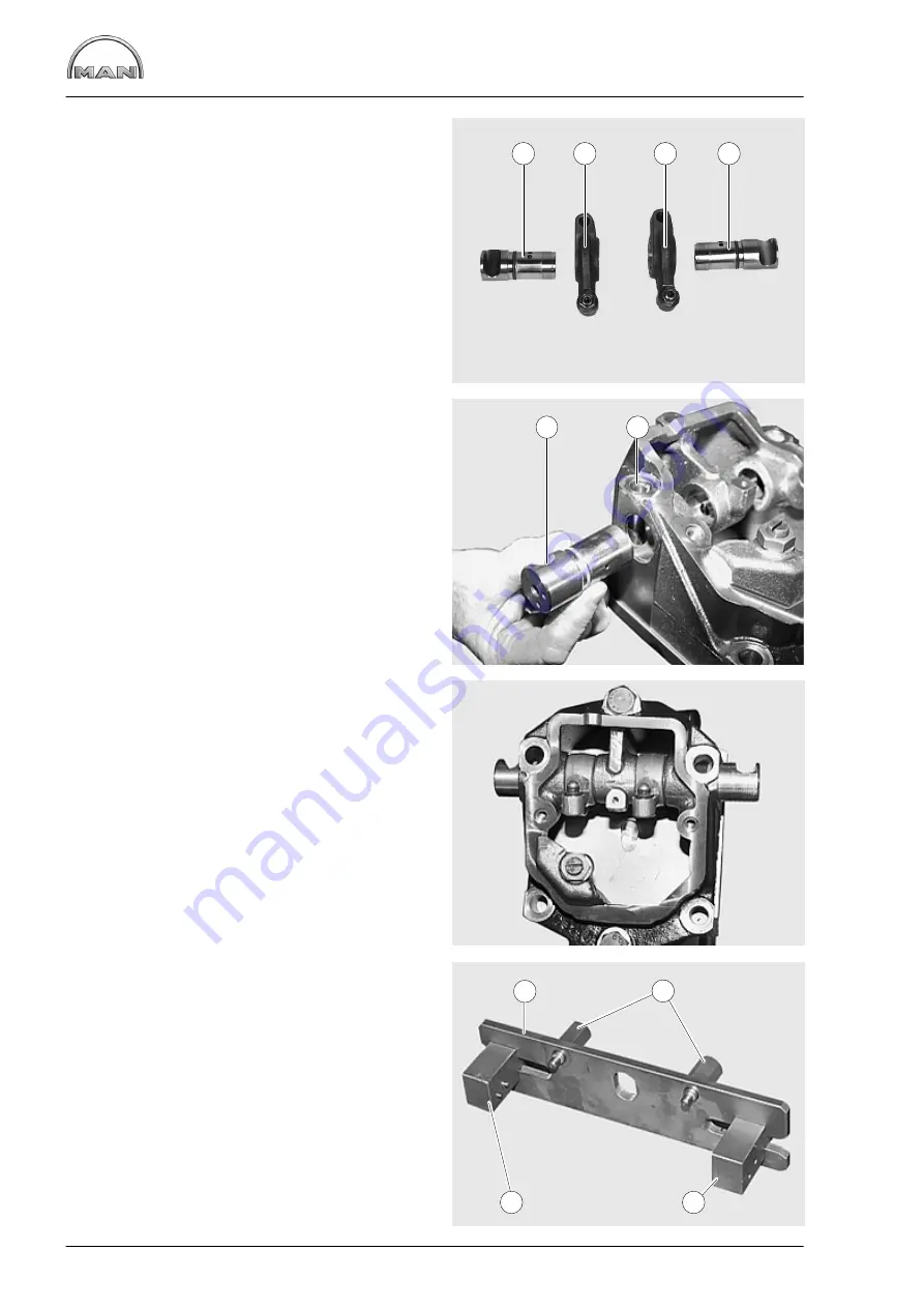
Dismantling and assembling the rocker arm mechanism
84
Fig. 5
À
Rocker arm shaft for exhaust valves
Á
Rocker arm shaft for inlet valves
Â
Rocker arm
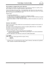
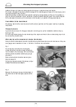
Assembling rocker arm mechanism
Fig. 6 and Fig. 7
Recesses
À
in the rocker arm shafts serve to ac-
commodate the cylinder head bolts
Á
.
Align the rocker arm shafts so that the holes for
the cylinder head bolts are kept free.
Lightly oil the shafts and O-rings.
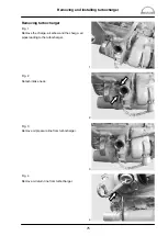
Fig. 8
Press
−
in device for the rocker arm shafts (special
tools).
À
Guide plate
Á
Mounting bolts
Â
Press
−
in part “A” for exhaust
−
side shaft
Ã
Press
−
in part “B” for intake
−
side shaft
2
1
3
3
1
2
1
2
3
4
Содержание D 2842 LE 620
Страница 1: ......
Страница 2: ......
Страница 20: ...Engine views D 2842 LE 620 18 7 1 2 4 3 5 6 7 1 2 4 11 9 10 8...
Страница 136: ...134...
Страница 137: ...135 Service Data...
Страница 163: ...161 Special tools...
Страница 164: ...Special tools 162 1 2 3 4 5 6 7 8 9 10 11 11 1 11 2 12 12 1 12 2 13 14...
Страница 166: ...Special tools 164 15 1 15 2 15 3 15 4 15 5 1 2 7 15 6 3 4 5 6 15 7...
Страница 168: ...Special tools 166 16 16 1 16 2 16 3 16 6 17 16 4 16 5 16 7 18 19 20 1 20 2 21 22 23 24 25 26 27 28...
Страница 170: ...Special tools 168 3 1 4 29 5 6 2 29 30 31 32 33 34 35...
Страница 172: ...Special tools 170 36 37 38 39 42 40 41 44 2 44 1 44 43 1 43 2 43 3 43 45 46...
Страница 178: ...176...
Страница 179: ......
Страница 180: ......


