


MAN B&W
2.04
Page 3 of 10
MAN Diesel
198 69 94-7.1
MAN B&W MC/MC-C-TII engines
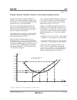
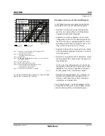
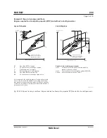
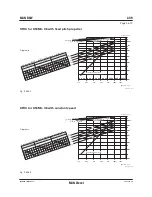
Line 4:
Represents the limit at which an ample air supply
is available for combustion and imposes a limita-
tion on the maximum combination of torque and
speed.
Line 5:
Represents the maximum mean effective pres-
sure level (mep), which can be accepted for con-
tinuous operation.
Line 6:
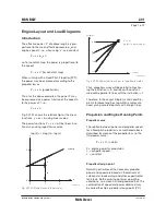
Propeller curve, clean hull and calm weather
– light running, used for propeller layout/design.
Line 7:
Represents the maximum power for continuous
operation.
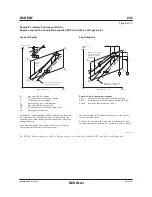
Limits for overload operation
The overload service range is limited as follows:
Line 8:
Represents the overload operation limitations.
The area between lines 4, 5, 7 and the heavy
dashed line 8 is available for overload running for
limited periods only (1 hour per 12 hours).
Line 9:
Speed limit at sea trial.
Limits for low load operation
The engine is able to operate down to around
25% of nominal L
1
speed.
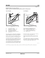
Recommendation
Continuous operation without limitations is al-
lowed only within the area limited by lines 4, 5, 7
and 3 of the Load diagram, except for CP propel-
ler plants mentioned in the previous section.
The area between lines 4 and 1 is available for
operation in shallow waters, heavy weather and
during acceleration, i.e. for nonsteady operation
without any strict time limitation.
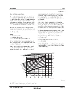
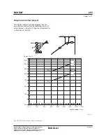
After some time in operation, the ship’s hull and
propeller will be fouled, resulting in heavier run-
ning of the propeller, i.e. the propeller curve will
move to the left of line 6 towards line 2, and extra
power is required for propulsion in order to keep
the speed of the ship.
In calm weather conditions, the extent of heavy
running of the propeller will indicate the need for
cleaning the hull and possibly polishing the pro-
peller.
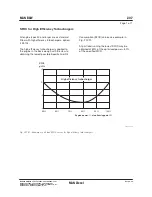
Once the specified MCR (and the optimising point)
have been chosen, the capacities of the auxiliary
equipment will be adapted to the specified MCR,
and the turbocharger specification and the com-
pression ratio will be selected.
If the specified MCR (and the optimising point) is
to be increased later on, this may involve a change
of the pump and cooler capacities, retiming of the
engine, change of the fuel valve nozzles, adjusting
the cylinder liner cooling, as well as rematching of
the turbocharger or even a change to a larger size
of turbocharger. In some cases, it can also require
larger dimensions of the piping systems.
It is therefore of the utmost importance to consid-
er, already at the project stage, if the specification
should be prepared for a later power increase.
This is to be indicated in item 4 02 010 of the Ex-
tent of Delivery.
Содержание B&W S50MC-C8-TII
Страница 4: ......
Страница 10: ......
Страница 18: ......
Страница 19: ...MAN B W MAN Diesel Engine Design 1 ...
Страница 20: ......
Страница 35: ...MAN B W MAN Diesel Engine Layout and Load Diagrams SFOC 2 ...
Страница 36: ......
Страница 52: ......
Страница 64: ......
Страница 65: ...MAN B W MAN Diesel Turbocharger Selection Exhaust Gas By pass 3 ...
Страница 66: ......
Страница 72: ......
Страница 73: ...MAN B W MAN Diesel Electricity Production 4 ...
Страница 74: ......
Страница 91: ...MAN B W Page of 1 MAN Diesel This section is not applicable Waste Heat Recovery Systems WHR 4 05 198 66 47 4 0 ...
Страница 106: ......
Страница 107: ...MAN B W MAN Diesel Installation Aspects 5 ...
Страница 108: ......
Страница 146: ......
Страница 170: ......
Страница 171: ...MAN B W MAN Diesel List of Capacities Pumps Coolers Exhaust Gas 6 ...
Страница 172: ......
Страница 192: ......
Страница 193: ...MAN B W MAN Diesel Fuel 7 ...
Страница 194: ......
Страница 208: ......
Страница 209: ...MAN B W MAN Diesel Lubricating Oil 8 ...
Страница 210: ......
Страница 223: ...MAN B W MAN Diesel Cylinder Lubrication 9 ...
Страница 224: ......
Страница 233: ...MAN B W MAN Diesel Piston Rod Stuffing Box Drain Oil 10 ...
Страница 234: ......
Страница 236: ......
Страница 237: ...MAN B W MAN Diesel Central Cooling Water System 11 ...
Страница 238: ......
Страница 243: ...MAN B W MAN Diesel Seawater Cooling System 12 ...
Страница 244: ......
Страница 254: ......
Страница 255: ...MAN B W MAN Diesel Starting and Control Air 13 ...
Страница 256: ......
Страница 262: ......
Страница 263: ...MAN B W MAN Diesel Scavenge Air 14 ...
Страница 264: ......
Страница 276: ......
Страница 277: ...MAN B W MAN Diesel Exhaust Gas 15 ...
Страница 278: ......
Страница 292: ......
Страница 293: ...MAN B W MAN Diesel Engine Control System 16 ...
Страница 294: ......
Страница 309: ...MAN B W MAN Diesel Vibration Aspects 17 ...
Страница 310: ......
Страница 324: ......
Страница 325: ...MAN B W MAN Diesel Monitoring Systems and Instrumentation 18 ...
Страница 326: ......
Страница 348: ......
Страница 349: ...MAN B W MAN Diesel Dispatch Pattern Testing Spares and Tools 19 ...
Страница 350: ......
Страница 388: ......
Страница 389: ...MAN B W MAN Diesel Project Suppport and Documentation 20 ...
Страница 390: ......
Страница 399: ...MAN B W MAN Diesel Appendix A ...
Страница 400: ......