


MAN B&W
17.05
Page 3 of 3
MAN Diesel
MAN B&W MC/MCC engines
198 59 045.2
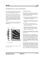
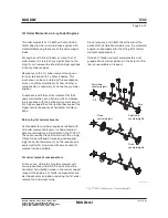
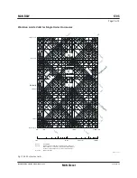
As the deflection shape for the Htype is equal
for each cylinder the N
th
order Htype guide force
moment for an Ncylinder engine with regular fir-
ing order is:
N x M
H(one cylinder)
For modelling purposes the size of the forces in
the force couple is:
Force = M
H
/L [kN]
where L is the distance between crankshaft level
and the middle position of the crosshead guide
(i.e. the length of the connecting rod.)
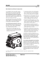
As the interaction between engine and hull is at
the engine seating and the top bracing positions,
this force couple may alternatively be applied in
those positions with a vertical distance of (L
Z
).
Then the force can be calculated as:
Force
Z
= M
H
/L
Z
[kN]
Any other vertical distance may be applied, so as
to accomodate the actual hull (FEM) model.
The force couple may be distributed at any
number of points in the longitudinal direction. A
reasonable way of dividing the couple is by the
number of top bracing and then applying the forc-
es at those points.
Force
Z, one point
= Force
Z, total
/N
top bracing, total
[kN]
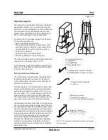
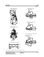
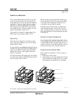
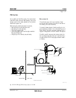
Xtype Guide Force Moment (M
X
)
The Xtype guide force moment is calculated
based on the same force couple as described
above. However as the deflection shape is twist-
ing the engine each cylinder unit does not contrib-
ute with an equal amount. The centre units do not
contribute very much whereas the units at each
end contributes much.
A socalled ‘Bimoment’ can be calculated (Fig.
17.05.02):
‘Bimoment’ =
Σ
[forcecouple(cyl.X) x distX]
in kNm
2
The Xtype guide force moment is then defined
as:
M
X
= ‘BiMoment’/L [kNm]
For modelling purpose the size of the four (4) forc-
es can be calculated:
Force = M
X
/L
X
[kN]
where:
L
X
is the horizontal length between ‘force points’
Similar to the situation for the Htype guide force
moment, the forces may be applied in positions
suitable for the FEM model of the hull. Thus the
forces may be referred to another vertical level L
Z
above crankshaft centre line. These forces can be
calculated as follows:
Force
Z, one point
=
M
x
x L
_____
L x L
[kN]
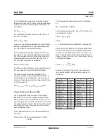
In order to calculate the forces it is necessary
to know the lengths of the connecting rods = L,
which are:
Engine Type
L in mm
K98MC6/7
3,220
K98MCC6/7
3,090
S90MCC7/8
3,270
K90MC-C6
3,159
S80MC6
3,504
S80MCC7/8
3,280
K80MCC6
2,920
S70MC6
3,066
S70MCC7/8
2,870
L70MCC7/8
2,660
S65MCC8
2,730
S60MC6
2,628
Engine Type
L in mm
S60MCC7/8
2,460
L60MCC7/8
2,280
S50MC6
2,190
S50MCC7/8
2,050
S46MC-C7/8
1,980
S42MC7
2,025
S40MCC9
1,770
S35MCC9
1,550
S35MC7
1,600
L35MC6
1,260
S26MC6
1,125
Содержание B&W S50MC-C8-TII
Страница 4: ......
Страница 10: ......
Страница 18: ......
Страница 19: ...MAN B W MAN Diesel Engine Design 1 ...
Страница 20: ......
Страница 35: ...MAN B W MAN Diesel Engine Layout and Load Diagrams SFOC 2 ...
Страница 36: ......
Страница 52: ......
Страница 64: ......
Страница 65: ...MAN B W MAN Diesel Turbocharger Selection Exhaust Gas By pass 3 ...
Страница 66: ......
Страница 72: ......
Страница 73: ...MAN B W MAN Diesel Electricity Production 4 ...
Страница 74: ......
Страница 91: ...MAN B W Page of 1 MAN Diesel This section is not applicable Waste Heat Recovery Systems WHR 4 05 198 66 47 4 0 ...
Страница 106: ......
Страница 107: ...MAN B W MAN Diesel Installation Aspects 5 ...
Страница 108: ......
Страница 146: ......
Страница 170: ......
Страница 171: ...MAN B W MAN Diesel List of Capacities Pumps Coolers Exhaust Gas 6 ...
Страница 172: ......
Страница 192: ......
Страница 193: ...MAN B W MAN Diesel Fuel 7 ...
Страница 194: ......
Страница 208: ......
Страница 209: ...MAN B W MAN Diesel Lubricating Oil 8 ...
Страница 210: ......
Страница 223: ...MAN B W MAN Diesel Cylinder Lubrication 9 ...
Страница 224: ......
Страница 233: ...MAN B W MAN Diesel Piston Rod Stuffing Box Drain Oil 10 ...
Страница 234: ......
Страница 236: ......
Страница 237: ...MAN B W MAN Diesel Central Cooling Water System 11 ...
Страница 238: ......
Страница 243: ...MAN B W MAN Diesel Seawater Cooling System 12 ...
Страница 244: ......
Страница 254: ......
Страница 255: ...MAN B W MAN Diesel Starting and Control Air 13 ...
Страница 256: ......
Страница 262: ......
Страница 263: ...MAN B W MAN Diesel Scavenge Air 14 ...
Страница 264: ......
Страница 276: ......
Страница 277: ...MAN B W MAN Diesel Exhaust Gas 15 ...
Страница 278: ......
Страница 292: ......
Страница 293: ...MAN B W MAN Diesel Engine Control System 16 ...
Страница 294: ......
Страница 309: ...MAN B W MAN Diesel Vibration Aspects 17 ...
Страница 310: ......
Страница 324: ......
Страница 325: ...MAN B W MAN Diesel Monitoring Systems and Instrumentation 18 ...
Страница 326: ......
Страница 348: ......
Страница 349: ...MAN B W MAN Diesel Dispatch Pattern Testing Spares and Tools 19 ...
Страница 350: ......
Страница 388: ......
Страница 389: ...MAN B W MAN Diesel Project Suppport and Documentation 20 ...
Страница 390: ......
Страница 399: ...MAN B W MAN Diesel Appendix A ...
Страница 400: ......