


MAN B&W
17.06
Page 1 of 2
MAN Diesel
MAN B&W S90MC-C/MEC, S80MC-C/MEC, S70MC/MC-C/MEC/MEGI,
L70MC-C/MEC, S65MEC/MEGI, S60MC/MC-C/MEC/MEGI/ME-B,
L60MC-C/MEC, S50MC/MCC/ME-B/ME-C, S46MC-C/ME-B, S42MC,
S40MC-C/ME-B, S35MC/MC-C/ME-B, L35MC, S26MC
198 42 257.6
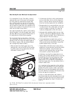
Axial Vibrations
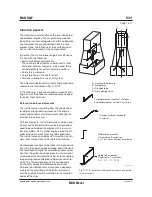
When the crank throw is loaded by the gas pres-
sure through the connecting rod mechanism, the
arms of the crank throw deflect in the axial direction
of the crankshaft, exciting axial vibrations. Through
the thrust bearing, the system is connected to the
ship’s hull.
Generally, only zeronode axial vibrations are of
interest. Thus the effect of the additional bending
stresses in the crankshaft and possible vibrations
of the ship`s structure due to the reaction force in
the thrust bearing are to be considered.
An axial damper is fitted as standard on all engines,
minimising the effects of the axial vibrations, 4 31 111.
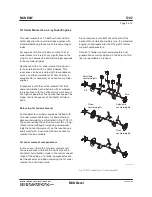
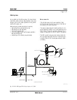
Torsional Vibrations
The reciprocating and rotating masses of the en-
gine including the crankshaft, the thrust shaft, the
intermediate shaft(s), the propeller shaft and the
propeller are for calculation purposes considered
as a system of rotating masses (inertias) intercon-
nected by torsional springs. The gas pressure of
the engine acts through the connecting rod mech-
anism with a varying torque on each crank throw,
exciting torsional vibration in the system with dif-
ferent frequencies.
In general, only torsional vibrations with one and
two nodes need to be considered. The main
critical order, causing the largest extra stresses
in the shaft line, is normally the vibration with
order equal to the number of cylinders, i.e., six
cycles per revolution on a six cylinder engine.
This resonance is positioned at the engine speed
corresponding to the natural torsional frequency
divided by the number of cylinders.
The torsional vibration conditions may, for certain
installations require a torsional vibration damper,
option: 4 31 105.
Based on our statistics, this need
may arise
for
the following types of installation:
• Plants with controllable pitch propeller
• Plants with unusual shafting layout and for spe-
cial owner/yard requirements
• Plants with 8cylinder engines.
The socalled QPT (Quick Passage of a barred
speed range Technique), is an alternative to a
torsional vibration damper, on a plant equipped
with a controllable pitch propeller. The QPT could
be implemented in the governor in order to limit
the vibratory stresses during the passage of the
barred speed range.
The application of the QPT, option: 4 31 108, has to
be decided by the engine maker and MAN Diesel
based on final torsional vibration calculations.
Sixcylinder engines, require special attention.
On account of the heavy excitation, the natural
frequency of the system with one-node vibration
should be situated away from the normal operat-
ing speed range, to avoid its effect. This can be
achieved by changing the masses and/or the stiff-
ness of the system so as to give a much higher, or
much lower, natural frequency, called undercritical
or overcritical running, respectively.
Owing to the very large variety of possible shaft-
ing arrangements that may be used in combina-
tion with a specific engine, only detailed torsional
vibration calculations of the specific plant can
determine whether or not a torsional vibration
damper is necessary.
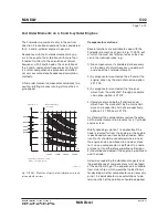
Undercritical running
The natural frequency of the one-node vibration
is so adjusted that resonance with the main criti-
cal order occurs about 3545% above the engine
speed at specified MCR.
Such undercritical conditions can be realised by
choosing a rigid shaft system, leading to a rela-
tively high natural frequency.
The characteristics of an undercritical system are
normally:
• Relatively short shafting system
• Probably no tuning wheel
• Turning wheel with relatively low inertia
• Large diameters of shafting, enabling the use of
shafting material with a moderate ultimate ten-
sile strength, but requiring careful shaft align-
ment, (due to relatively high bending stiffness)
• Without barred speed range
Содержание B&W S50MC-C8-TII
Страница 4: ......
Страница 10: ......
Страница 18: ......
Страница 19: ...MAN B W MAN Diesel Engine Design 1 ...
Страница 20: ......
Страница 35: ...MAN B W MAN Diesel Engine Layout and Load Diagrams SFOC 2 ...
Страница 36: ......
Страница 52: ......
Страница 64: ......
Страница 65: ...MAN B W MAN Diesel Turbocharger Selection Exhaust Gas By pass 3 ...
Страница 66: ......
Страница 72: ......
Страница 73: ...MAN B W MAN Diesel Electricity Production 4 ...
Страница 74: ......
Страница 91: ...MAN B W Page of 1 MAN Diesel This section is not applicable Waste Heat Recovery Systems WHR 4 05 198 66 47 4 0 ...
Страница 106: ......
Страница 107: ...MAN B W MAN Diesel Installation Aspects 5 ...
Страница 108: ......
Страница 146: ......
Страница 170: ......
Страница 171: ...MAN B W MAN Diesel List of Capacities Pumps Coolers Exhaust Gas 6 ...
Страница 172: ......
Страница 192: ......
Страница 193: ...MAN B W MAN Diesel Fuel 7 ...
Страница 194: ......
Страница 208: ......
Страница 209: ...MAN B W MAN Diesel Lubricating Oil 8 ...
Страница 210: ......
Страница 223: ...MAN B W MAN Diesel Cylinder Lubrication 9 ...
Страница 224: ......
Страница 233: ...MAN B W MAN Diesel Piston Rod Stuffing Box Drain Oil 10 ...
Страница 234: ......
Страница 236: ......
Страница 237: ...MAN B W MAN Diesel Central Cooling Water System 11 ...
Страница 238: ......
Страница 243: ...MAN B W MAN Diesel Seawater Cooling System 12 ...
Страница 244: ......
Страница 254: ......
Страница 255: ...MAN B W MAN Diesel Starting and Control Air 13 ...
Страница 256: ......
Страница 262: ......
Страница 263: ...MAN B W MAN Diesel Scavenge Air 14 ...
Страница 264: ......
Страница 276: ......
Страница 277: ...MAN B W MAN Diesel Exhaust Gas 15 ...
Страница 278: ......
Страница 292: ......
Страница 293: ...MAN B W MAN Diesel Engine Control System 16 ...
Страница 294: ......
Страница 309: ...MAN B W MAN Diesel Vibration Aspects 17 ...
Страница 310: ......
Страница 324: ......
Страница 325: ...MAN B W MAN Diesel Monitoring Systems and Instrumentation 18 ...
Страница 326: ......
Страница 348: ......
Страница 349: ...MAN B W MAN Diesel Dispatch Pattern Testing Spares and Tools 19 ...
Страница 350: ......
Страница 388: ......
Страница 389: ...MAN B W MAN Diesel Project Suppport and Documentation 20 ...
Страница 390: ......
Страница 399: ...MAN B W MAN Diesel Appendix A ...
Страница 400: ......