20
OPERATING SEQUENCE
The operating sequences for the heating, cooling, and
fan modes are described below. Refer to the fi eld and
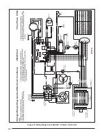
furnace wiring diagrams (Figures 12 or 13, pages 28 - 29).
Heating Mode
1. On a call for heat, the thermostat closes and applies
24 VAC to terminal W on the control board.
2. The control board checks for continuity on the 24 VAC
limit control circuit, over-temperature limit switch, fl ame
rollout switches, and blocked vent switch in series. If an
open limit is detected, the control board will energize
the inducer blower. All other system functions will be
inoperable until the limit circuit closes. While the limit
is open, the red LED will pulse at a rate of 1 blink per
unit time.
3. The furnace control checks for continuity (24 VAC)
across the pressure switch. If the pressure switch is
closed, the heat mode sequence will not continue. If it
remains closed for 10 seconds, the red LED will fl ash
3 times repetitively until the fault condition clears.
4. The inducer energizes (if pressure switch is open).
5. The pressure switch will close. If the pressure switch
does not close after 10 seconds, the fault LED will
fl ash 2 times and the inducer will continue to run until
the switch is closed.
6. The inducer will pre-purge for 30 seconds and then
the igniter will start its warm-up as follows:
Initial Power up: After 30 seconds of igniter warm-up,
the gas valves (24 VAC) will open. The igniter circuit
will stay energized for 3 seconds after the gas valve
opens.
After Initial Power up: The control has a programmed
adaptive ignition feature which varies the warm-up
period as follows: If ignition is successful the warm-up
is reduced by 3 seconds on each subsequent call for
heat until ignition failure occurs. Upon ignition failure,
the warm-up is increased by 3 seconds on the next try.
If successful, the timing remains fi xed at this level. In
general, whenever ignition failure occurs the warm-up
interval is increased by 3 seconds on the next try. And
if successful, it remains there. Minimum and maximum
warm-up time limits are set at 6 and 54 seconds.
7. The furnace control must prove fl ame via the fl ame
sensor 5 seconds after the gas valves open. If fl ame
is sensed, burners are on and the igniter cools off. If
no fl ame is sensed, the gas valve closes immediately
and the inducer continues to run. A second trial for
ignition (step 6) begins. If no fl ame is sensed on the
fi fth try for ignition, the furnace control is locked and the
red LED will blink 4 times repetitively. The thermostat
must be opened for at least ten seconds to reset the
furnace control after a lock out. Otherwise, the furnace
will attempt another ignition sequence in 1 hour.
them to the service ports on the unit. Refrigerant charging
must be done by qualifi ed personnel familiar with safe
and environmentally responsible refrigerant handling
procedures.
Table 6. Manifold Pressure (in W.C.) for Natural Gas
Manifold Pressure (in W.C.) for
Natural Gas Installations
Altitude above
sea level
Heating Value Btu/cu. ft.
800 to 899
900 to 999 1,000 to 1,100
zero to 1,999 FT
3.5
3.5
3.5
2,000 to 4,999 FT
3.5
3.5
3.5
5,000 to 5,999 FT
3.5
3.5
3.0
6,000 to 7,999 FT
3.5
3.2
2.8
8,000 to 10,000 FT
3.0
2.8
2.5
Table 7. Manifold Pressure (in W.C.) for LP Gas
Manifold Pressure (in W.C.) and Orifi ce Sizes
for LP/Propane Gas Installations
Altitude above
sea level
Manifold
Pressure
Orifi ce
Size
zero to 1,999 FT
10.0
54
2,000 to 4,999 FT
8.5
54
5,000 to 5,999 FT
10.0
55
6,000 to 7,999 FT
9.0
55
8,000 to 10,000 FT
8.5
55
NOTE: Manifold pressure based on sea level LP heating value
of 2,500 Btu/cu. ft.
3
Manifold Pressure Adjustment
The manifold pressure must be set to the appropriate
value for your installation. To adjust the manifold pressure:
1. Obtain the required manifold pressure setting. Use
Table 6 for natural gas or Table 7 for LP/propane gas.
NOTE: The values listed in the tables are based on sea
level values. At higher altitudes, the heating value of gas
is lower than the sea level heating value.
2. Remove the regulator cap. Turn the high fire
adjusting screw clockwise to increase the pressure or
counterclockwise to reduce the pressure.
3. Replace the regulator cap after adjustments are
complete.


