6
11.
Do not leave the tool running. Operate the tool
only when hand-held.
12.
Do not point the tool at any one in the area
when operating. The bit could fly out and
injure someone seriously.
13.
Do not touch the bit or parts close to the bit
immediately after operation; they may be
extremely hot and could burn your skin.
14.
Some material contains chemicals which may
be toxic. Take caution to prevent dust
inhalation and skin contact. Follow material
supplier safety data.
SAVE THESE INSTRUCTIONS.
WARNING:
DO NOT let comfort or familiarity with product
(gained from repeated use) replace strict adherence
to safety rules for the subject product. MISUSE or
failure to follow the safety rules stated in this
instruction manual may cause serious personal
injury.
FUNCTIONAL DESCRIPTION
CAUTION:
•
Always be sure that the tool is switched off and
unplugged before adjusting or checking function on
the tool.
Switch action
Fig.1
CAUTION:
•
Before plugging in the tool, always check to see
that the switch trigger actuates properly and
returns to the "OFF" position when released.
To start the tool, simply pull the switch trigger. Release
the switch trigger to stop.
Lighting up the lamp
For Model HR3541FC
Fig.2
CAUTION:
•
Do not look in the light or see the source of light
directly.
Pull the switch trigger to turn on the light. The lamp
keeps on lighting while the switch trigger is being pulled.
The lamp turns off 10 - 20 seconds after releasing the
trigger.
NOTE:
•
Use a dry cloth to wipe the dirt off the lens of lamp.
Be careful not to scratch the lens of lamp, or it may
lower the illumination.
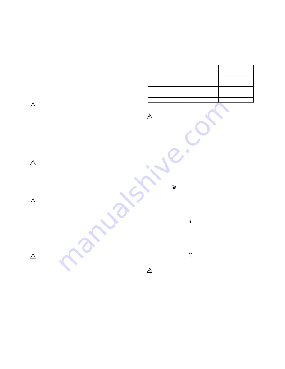
Speed change
Fig.3
The revolutions and blows per minute can be adjusted
just by turning the adjusting dial. The dial is marked 1
(lowest speed) to 5 (full speed).
Refer to the table below for the relationship between the
number settings on the adjusting dial and the
revolutions/blows per minute.
5
4
3
2
1
Number on
adjusting dial
Revolutions per
minute
Blows per minute
630
590
480
370
315
3,300
3,100
2,500
1,900
1,650
008550
CAUTION:
•
If the tool is operated continuously at low speeds
for a long time, the motor will get overloaded,
resulting in tool malfunction.
•
The speed adjusting dial can be turned only as far
as 5 and back to 1. Do not force it past 5 or 1, or
the speed adjusting function may no longer work.
Selecting the action mode
Rotation with hammering
Fig.4
For drilling in concrete, masonry, etc., depress the lock
button and rotate the change lever so that the pointer
points to the
symbol. Use a tungsten-carbide tipped
bit.
Rotation only
Fig.5
For drilling in wood or metal, materials, etc., depress the
lock button and rotate the change lever so that the
pointer points to the
symbol. Use a twist drill bit or
wood bit.
Hammering only
Fig.6
For chipping, scaling or demolition operations, depress
the lock button and rotate the change lever so that the
pointer points to the
symbol. Use a bull point, cold
chisel, scaling chisel, etc.
CAUTION:
•
Do not rotate the change lever when the tool is
running under load. The tool will be damaged.
•
To avoid rapid wear on the mode change
mechanism, be sure that the change lever is
always positively located in one of the three
action mode positions.
Torque limiter
The torque limiter will actuate when a certain torque
level is reached. The motor will disengage from the
output shaft. When this happens, the bit will stop turning.
Содержание HR3540C
Страница 53: ...53 ...
Страница 54: ...54 ...
Страница 55: ...55 ...
Страница 56: ...56 Makita Corporation Anjo Aichi Japan 884815C986 ...