


O ring
Wad (Wave washer)
Gasket (Flat washer)
M6x40
Hex socket
head bolt
P
6
/ 1
0
R
epair
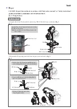
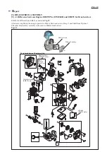
ASSEMBLING
(4A) In case of replacing the Engine, adjust the length of Engine’s drive shaft as drawn in
Fig. 9
before mounting
Pump frame to the Engine.
Fig. 8
Fig. 9
(4) Assemble Pump frame as drawn in
Fig. 8
.
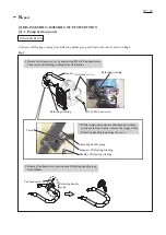
1. Pass each M6x40 Hex socket head bolt through
Wave washer, Flat washer and O ring.
Note
: Be careful not to give damage to O ring
when mounting it to the bolt.
2. Mount one each of Washers (0.5mm thick and 0.2mm thick) to Drive shaft of the Engine.
Then assemble Pump frame to the Engine by tightening it with four M6x40 socket head bolts.
Note
: Fastening torque of their bolts have to be
2.5 -3.5 N.m
.
Washers (0.5mm thick
and 0.2mm thick)
Drive shaft
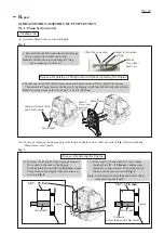
1A. Measure the length from the stepped portion of
Drive shaft to the neck of the Engine.
If the length is between
34.7 to 35.8 mm
, mount
Pump frame to the Engine without Washers as
drawn in
Fig. 8
.
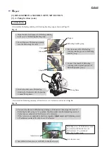
2A. If the length is shorter than 34.7 mm, adjust
the length to
34.7 ~ 35.8 mm
by adding some
Washer(s) as drawn below. Then mount Pump
frame to the Engine as drawn in
Fig. 8
.
Note
: Use Washer(s) 0.5mm thick and 0.2mm thick)
when adjusting the length.
Pump frame
M6x40
Hex socket
head bolt
(4 pcs.)
34.7 ~ 35.8 mm
34.7 ~ 35.8 mm
Drive shaft
In case of replacing the Engine
In case of repairing of Pump section without replacing the Engine
Drive shaft
Engine
[3] DISASSEMBLY/ASSEMBLY OF PUMP SECTION
[3] -1. Pump Section (cont.)
Engine
Washer(s)
(0.5mm thick and 0.2mm thick)


