P 3 / 9
R
epair
[3] DISASSEMBLY/ASSEMBLY
[3] -1. Disassembling/Assembling Hammering Mechanism
Fig. 3
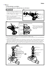
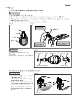
1) Remove Belt clip by unscrewing Screw M4x12.
After removing Bumper and Hammer case cover
by hand, then remove Rear cover by unscrewing
two PT3x16 Tapping screws. (Fig. 2)
2) Shift the tail of torsion spring from Carbon brush
onto the notch in Brush holder.
Then pull off Receptacle from Brush holder.
Now Carbon brush can be removed from Brush
holder. (Fig. 3)
3) Separate Housing (R) from Housing (L) by removing eight PT3x16 Tapping screws.
4) Remove the assembly of the Hammer case section and the Motor section from Housing (L), then separate the Hammer
case from the Motor section.
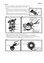
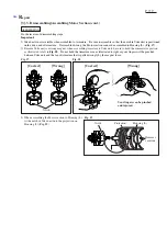
5) Attach a pair of Vise plate (No.1R041) to vise. Fix Socket 32-50 in vise securely. Then put the Hammer case section
on Socket 32-50 while fitting the hexagonal portion of Bearing box in Socket 32-50. Fit Socket 30-78 over the hex-
agonal portion of Hammer case. Then, by turning Socket 30-78 with Torque wrench shaft 20-90N.m (No.1R223) and
Ratchet head with 12.7mm square (No.1R224) clockwise, the Hammer case section can be disassembled. (Fig. 4)
1
2
A
[Brush holder section (View from A)]
Fig. 4
DISASSEMBLING
Rear cover
Tapping screw
PT3x16 (2 pcs)
Hammer case cover
Hammer case
Bumper
Belt clip
Fig. 2
Screw M4x12
Carbon
brush
Carbon
brush
Torsion
spring
1. Shift the tail of Torsion spring
onto the notch of Brush holder.
2. Then pull off Receptacle from
Brush holder.
Hammer case
No.1R223
No.1R224
Socket 30-78
Fit socket 30-78 over
this hex portion.
Vise plate
Vise
Socket 32-50
Vise plate
Bearing box
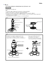
Internal gear 51
O ring 40
Bearing box
Hammering mechanism
Hammer case


