P 6 / 9
R
epair
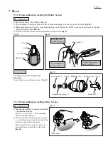
[3] -2. Disassembling/Assembling Bit Holder Section
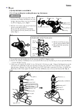
1) Put A
nvil on Pipe 30 (No.1R232). (Fig. 13)
2) Put your thumb on the top of Sleeve so that Compression spring 13 does not pop out of Sleeve. (
Fig. 14)
3) While e
xpanding Ring spring 11 using Retaining ring S and R pliers (No.1R291). raise the opposite side of the Ring
spring with index finger. (
Fig. 14)
4)
Now the bit holder section can be disassembled as illustrated in Fig. 15.
Do the reverse of disassembling steps.
Fig. 13
Fig. 14
ASSEMBLING
DISASSEMBLING
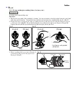
[3] -3. Disassembling/Assembling Motor Section
1) Separate the assembly of Armature and Yoke
unit from the machine
.
(Refer to 1) to 4) of [3] -1. Disassembling
Hammering Mechanism.)
2) Put the assembly of Yoke unit and Armature
on a work bench so that the drive end of the
Armature touches the work bench.
Then separate Yoke unit from armature by
pressing it down towards the work bench.
(
Fig. 16)
.
DISASSEMBLING
No.1R232
Anvil
Hammer case
Sleeve
Ring spring 11
Sleeve
Important:
Do not forget to mount Nylon washer. (Fig. 15)
Put your thumb on
the top of Sleeve.
Raise this side
with index finger.
Expand Ring spring 11
using No.1R291.
Fig. 15
Hammer case
Nylon washer
Sleeve
Steel ball 3.5
Anvil
Compression spring 13
Flat washer 12
Yoke unit
Fig. 16


