background image

R

epair

P 10/15

[3] DISASSEMBLY/ASSEMBLY
[3] -5. Motor and Gear Section

DISASSEMBLING

ASSEMBLING

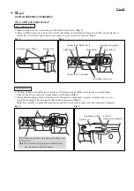
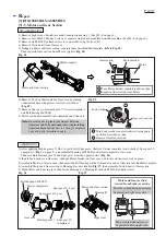
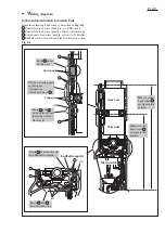
1) Remove Light cover, Switch lever and Compression spring 2. (See [3] -1 on page 4.)
2) Remove four M4x22 Pan head screws to separate Angle head complete from the machine. (See [3] -3 on page 6.)
3) Remove six M3x20 Pan head screws to separate Housing (L) from (R).
4) Remove Switch unit from Gear case.
5) Lifting up Motor and Gear section, separate them from Endbell complete. (left in Fig. 24)
    Then separate Gear section from Motor. (right in Fig. 24)

6) Remove Lock washer located in Gear case by turning
    counterclockwise with pliers or slotted screwdriver. 
    (Fig. 25)
7) Remove Spur gears, Internal gear 47, Carrier complete A
    and Ball bearing 6805LLB.
8) Motor can be disassembled into Armature and Yoke unit.

1) After applying Makita grease N No.2 to teeth of all Spur gears, shafts of Carrier complete A and shafts of Spur gear 20
    complete A (Fig. 1 on page 3), assemble Ball bearing 6805LLB and Carrier complete to Gear case.
    Then assemble Internal gear 47 and Spur gears from the opposite side. (Fig. 26)
2) Install Lock washer on Gear case, then put Motor bracket on Gear case, and turn it clockwise to lock in place. 
3) Assemble Motor to Gear section, then insert the Ball bearing on the Commutator end of Armature into Endbell complete.
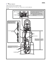
4) Assemble Motor and Gear section to Housing R as described in Fig. 27, then assemble Switch unit to Gear section.
5) Mount Plate and Lens in place, then fasten Housing L to Housing R with six M3x20 Pan head screws.

Fig. 27

Fig. 26

Fig. 24

Gear section

Motor bracket

Turn Motor bracket counterclockwise, then
Separate Gear section from Motor

Fig. 25

Lock washer

Turn Lock washer counterclockwise using pliers
or slotted screwdriver, then
Remove from Gear section.

Gear case section

Motor

Endbell complete

Motor and Gear section

Carrier complete A

Ball bearing 6805LLB

Internal gear 47 Spur gear 20

complete A

Spur gear 18 (3 pcs)

Spur gear 13 (3 pcs)

Gear case

Note: 

B

e careful not to pinch your fingers between

          Armature and Yoke unit when removing/installing
          Armature because 

Yoke unit is a strongly magnetic

          body and pulls Armature strongly.

Light cover

Housing R

Motor and Gear section

viewed from Light cover side

Motor and Gear section

The notch in Yoke unit must
be placed on Housing R side.

The ribs to hold Switch unit must
be placed on Light cover side.

Содержание BFL060F

Страница 1: ... load speed rpm min 1 450 15 22 with DC18RA 150 1 5 1 1 7 2 3 3 1 3 7 2 Battery Driving shank mm Net weight kg lbs LED Job light Torque adjustment Torque range N m in lbs 1 5 6 13 53 Hard joint Soft joint Yes Yes See the list above Electric brake Soft start Yes Reverse switch Yes Yes Cell Charging time min Voltage V Capacity Ah Ni MH 9 6 2 0 3 3 Max output W 1 with 2 0Ah battery BH1220C 2 with 3 3...

Страница 2: ...6900LLB 1R269 Bearing extractor 1R291 Retaining ring S and R pliers Removing installing Retaining ring S 10 1R173 Retaining ring R pliers RT 1 Removing installing Retaining ring R 22 1R145 L type Torx wrench Loosening tightening Torx countersunk head screw M5x10 1R314 Torx bit VT 25 1R219 Torque wrench shaft 7 23N m 1R220 Ratchet head 9 5 for 1R219 1R222 Socket adapter 1R219 Torque wrench shaft 7 ...

Страница 3: ...hesive Bearing retainer 14 23 Threaded portion Torx C S H screw M5x10 Threaded portion Whole surface Whole surface Teeth portion and three shaft pins for Teeth portion Surface that contacts Steel ball 5 0 3 pcs Steel ball 4 3 pcs Whole surface Steel ball 3 13 pcs O ring 14 Spur gear 13 3 pcs Spur gear 20 complete A Spur gear 18 3 pcs Teeth portion that engages with and Internal gear 47 28 Three sh...

Страница 4: ... in the notch of Angle head complete assemble Light cover to Angle head complete by screwing two M4x8 Pan head screws Fig 5 Note Be careful not to pinch the slack portion of Lead wires between Light cover and Angle head complete Pan head screw M4x8 Light cover Connector of LED circuit Connector of Controller LED circuit Controller s lead wire Light holder tab 3 1 LED Job Light Section 3 DISASSEMBL...

Страница 5: ... Bearing retainer 14 23 Fig 1 on page 3 Then assemble Flat washer 6 to Spindle complete Refer to Fig 8 Assembling of Spindle complete section has been completed 4 Clamp the flats of Angle head complete securely in a vise to which 1 set of 1R041 is attached then assemble Spindle complete section to Angle head complete by turning Bearing retainer 14 23 counter clockwise using 1R219 1R220 1R222 and A...

Страница 6: ...15 Fig 14 Fig 16 3 Using 1R173 remove Retaining ring R 22 that retains Spiral bevel gear 9 section in Angle head complete Fig 14 Spiral bevel gear 9 section can now be removed by tapping the end surface of Angle head complete with plastic hammer Fig 15 Compression spring 5 Retaining ring R 22 Spiral bevel gear 9 section Angle head complete Pan head screws M4x22 4 pcs Housing Clutch section Clutch ...

Страница 7: ...ble as illustrated to left in Fig 17 Note 2 Use 1R034 and arbor press when assembling Ball bearing 6900LLB to Spiral bevel gear 9 Fig 18 3 3 Spiral Bevel Gear 9 Section cont 3 DISASSEMBLY ASSEMBLY ASSEMBLING Fig 18 Fig 17 Spacer Needle baring 1210 Ball bearing 6900 LLB 1R034 arbor press Spiral bevel gear 9 Spacer Needle baring 1210 Spiral bevel gear 9 Correct Wrong ...

Страница 8: ... from Angle head complete Refer to Figs 12 13 on page 6 2 Insert Torque adjust tool 765027 4 into the hole of Adjust ring complete and turn it counterclockwise to remove Lock nut M12 the pressure of Compression spring 19 will be decreased and Lock nut M12 can now be removed by turning it clockwise by hand Fig 19 3 Remove Adjust ring complete Flat washer 18 Compression spring 19 from Spindle Fig 20...

Страница 9: ... the disassembling steps Note When fastening Torx countersunk screw M5x10 to Spindle do as described in Fig 23 Apply Makita grease N No 2 to all Steel balls and the Spindle s threaded portion for engaging with Lock nut M12 before assembling Fig 1 on page 3 Be careful not to put the grease in the threaded hole of Spindle ASSEMBLING Spindle Torx countersunk head screw M5x10 Clean up this threaded po...

Страница 10: ...Lock washer on Gear case then put Motor bracket on Gear case and turn it clockwise to lock in place 3 Assemble Motor to Gear section then insert the Ball bearing on the Commutator end of Armature into Endbell complete 4 Assemble Motor and Gear section to Housing R as described in Fig 27 then assemble Switch unit to Gear section 5 Mount Plate and Lens in place then fasten Housing L to Housing R wit...

Страница 11: ...e direction of the gray arrow while turning it counterclockwise Fig 28 DISASSEMBLING 1 Assemble Micro switch to Reverse switch by fastening the screw to the recommended torque of 0 29 0 34N m 2 Fitting the boss of Reverse switch in the concave portion of F R change lever assemble F R change lever to Reverse switch Fig 29 3 Assemble Main switch section to Housing R Fig 28 screw Micro switch On off ...

Страница 12: ... LED unit Switch unit Buzzer unit Lamp unit Indication lamp Controller Micro switch On off Switch COM NO Binding tapes Binding tapes S2 S1 M2 M1 M2 Reverse switch DC Motor Color index of lead wires sheath Black White Red Orange Gray Blue Yellow Purple ...

Страница 13: ...r s lead wires purple yellow to Switch unit Controller s lead wires blue yellow to Lamp unit Right side of Main switch 1 2 Lead wire holder Fix the following Lead wires securely with the Lead wire holders on Main switch 1 Endbell s lead wire black 2 Controller s lead wire white Rear side of Main switch rib rib Route Lead wires beside this rib Put Connectors between these ribs Controller Buzzer cir...

Страница 14: ...it Switch unit s lead wires purple yellow to Controller Endbell s lead wires red and black to Reverse switch Connector rib Put the following parts in this space Connectors Slack portion of Route under Switch unit Route and between the rib and the inside wall of Housing R Endbell complete Route and between these ribs rib Route between this rib and Endbell complete Make sure that Lead wires are tigh...

Страница 15: ...at Lead wires are tight in this portion Route Controller s lead wires blue gray to LED circuit as described in Fig D 4 Route Lead wires between these ribs Route Lead wires under the two tabs Switch unit rib Put Connectors and the slack portion of Lead wires in the space Note Be careful not to put them on LED circuit nor the ribs around LED circuit ...

Отзывы: