


P 12/15
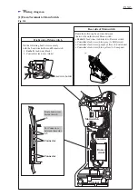
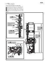
Fig. D-1
C
ircuit diagram
= Connector
T
erminal
LED unit
Switch unit
Buzzer unit
Lamp unit
(Indication lamp)
Controller
Micro switch
(On/off Switch)
COM
NO
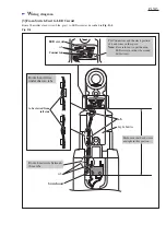
Binding tapes
Binding tapes
S2
S1
M2
M1
M2
Reverse
switch
DC
Motor
Color index of lead wires' sheath
Black
White
Red
Orange
Gray
Blue
Yellow
Purple