R
epair
P 7 / 17
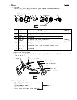
Fig. 25
Fig. 26
Fig. 27
Fig. 28
Fig. 29
Fig. 30
Fig. 31
Fig. 32
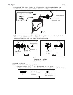
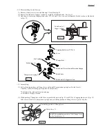
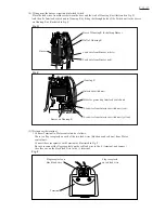
(2) Mount steel balls and cam B and cam A in the order of Fig. 25, Fig. 26, Fig. 27 and Fig.28.
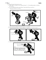
(3) Before mounting, apply MAKITA grease N. No.2 to 13 pcs. of steel balls 3.0.
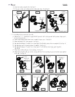
Assemble steel balls 3.0, flat washer 7 and torx counter sunk head screw M5x10 as illustrated in Fig. 29, Fig.30
and Fig. 31.
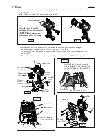
(4) Before mounting, apply MAKITA grease N. No.2 to threaded portion of spindle.
Assemble compression spring 19, flat washer 18 and adjust ring complete and lock nut 12
in the order of Fig. 31 and Fig. 32.
Steel balls 5
(3 pcs.)
Mount steel balls 5
to spindle.
Mount cam D to spindle
with aligning its 3 grooves
with steel balls 5.
Mount steel balls 4
to cam B.
Mount cam A.
Cam B
Steel balls 4
(3 pcs.)
Steel balls 3.0
(13 pcs.)
Mount steel balls 3.0
to cam A.
Mount flat washer 7
to cam A.
Pay attention, not to spot
the screw hole of spindle
with the grease, when
assembling steel balls.
Flat washer 7
Torx counter sunk
head screw M5x10
Apply here the
adhesive by 0.1CC,
before screwing.
After applying 0.1cc (3 drops) of
adhesive, "Lock tight 603" in the
screw hole, fasten flat washer 7
with torx counter sunk head
screw M5x10.
The fastening torque for the
screw is 8 - 10 N.m.
Compression
spring 19
Adjust ring
complete
Fig. 31
Lock nut 12
While pressing lock nut 12 strongly, turn torque adjust tool
clockwise. Then, lock nut M12 turns anti-clockwise
and fastened to spindle.
Cam A
Flat
washer 18


